1. Boolean Algebra (10 points)
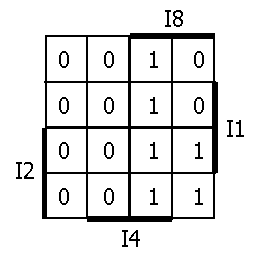
You are working with binary-coded decimal numbers and need to derive expressions that will indicate when an invalid number is present, that is, any 4-bit value greater than 9. The function is F = ( {I8, I4, I2, I1} > 4'b1001). Note that I8 is the high-order bit. Fill in the Karnaugh map below for F.

(a) Derive a minimal sum-of-products expression. (2 points)
I8 I4 + I8 I2
(b) List the essential prime implicants
for this expression. (2 points)
The two terms, I8 I4 and I8 I2, are both essential prime implicants.
(c) Derive a minimal product-of-sums
expression. (2 points)
(I8) (I4 + I2)
(d) Applying the rules of Boolean
algebra transform the minimal P-o-S expression into the minimal S-o-P expression
thereby proving that they are equivalent. (2 points)
Applying the distributive law to the answer for part (c) yields the answer to part (a).
(e) Draw a circuit diagram
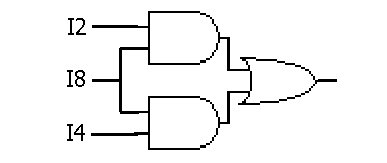
for the mimized S-o-P function using only AND, OR, and NOT gates. (2 points)
2. Arithmetic (25 points)
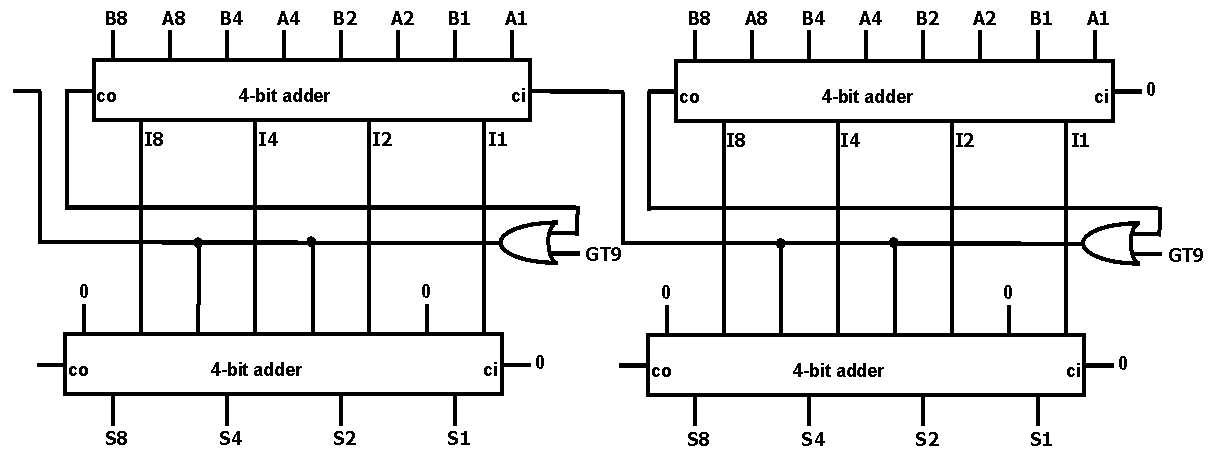
Construct an adder that adds two 2-digit binary-coded decimal (BCD) numbers. You have 4-bit adder modules available (with carry-in and carry-out) and any basic gates you require. Hint: when adding two BCD digits that yield a result greater than 9, you can correct the value by adding an extra 6, of course, this may also cause a carry (e.g., 5 + 6 = 11 which, with another 6, yields 17 or a result of 1 with a carry of 1).
To correct a BCD addition, we need
to be able to tell if the result of adding two digits is greater than 9.
This is precisely what the circuit of problem 1 detects. Therefore,
we add the two low-order digits, detect if the result is greater than 9
(labelled GT9 in the diagram below) or if it already caused a carry-out
(meaning the result was greater than 16) and then selectively add either
0 (if the digits added up to less than 9) or 6 (if they added up to more
than 9). The carry for the addition is the same signal that detected
the result was greater than 9 and caused an extra 6 to be added.
3. Combinational Logic (20 points)
Construct a circuit that determines whether a year is a leap year or not. This is to be used in conjunction with the example we started on in the first week. The current leap year system was established in 1582 by Pope Gregory I (hence, the name "Gregorian calendar") so we only need to consider years greater than 1582. Leap years are all the years divisible by 4. However, years divisible by 100 are not leap years. As a final correction, years divisible by 400 are leap years. Thus, the rule is:
Its a leap year if divisible by 4 and greater than 1582, unless the year is divisible by 100 and not by 400.
The circuit has the year as input (encoded as a BCD number of 4 digits or 16 bits) and the leap year flag as an output. Assume that the year is greater than 1582 and that this bound does not need to be checked.
(a) Construct a circuit that determines if the year is divisible by 4. (5 points)
We only need to look at the low-order two digits of the year to determine if it is divisible by 4. All years ending in 00, 04, 08, 12, 16, 20, etc. are divisible by 4. A simple way to determine this is as follows: if the tens digit is even, then the number is divisible by 4 if the ones digit is 0, 4, or 8; if the tens digit is odd, then the number is divisible by 4 if the ones digit is 2 or 6. This easily translates into the following Boolean expression (where YT1 is the year's tens digit low-order bit, YO8 is the high-order bit of year's ones digit, etc.):
YT1' (YO8' YO4' YO2' YO1' + YO8' YO4 YO2' YO1' + YO8 YO4' YO2' YO1')If we then consider that digits with values of 10 to 15 will never occur, we can simplify further to yield:
+ YT1 (YO8' YO4' YO2 YO1' + YO8' YO4 YO2 YO1')
YT1' YO2' YO1' + YT1 YO2 YO1'
(b) Construct a circuit that determines
if the year is divisible by 100. (5 points)
Given that we have a BCD encoding of the year, this just requires checking that all the bits of the two low-order digits of the year are both 0:
YT8' YT4' YT2' YT1' YO8' YO4' YO2' YO1'
(c) Construct a circuit that determines
if the year is divisible by 400. (5 points)
This combines the results of part (b) applied to the low-order digits of the year and the result of part (a) applied to the high-order two digits of the year to yield (where YM and YH are the thousands and hundreds digits of the year):
(YM1' YH2' YH1' + YM1 YH2 YH1') (YT8' YT4' YT2' YT1' YO8' YO4' YO2' YO1' )
(d) Finally, construct a circuit
that outputs the leap year flag to be used by the month module we discussed
in class. (5 points)
The leap year flag can be constructed from the results of parts (a), (b), and (c) (named A, B, and C, respectively):
leap_year_flag = A(B C')' = AB' + CNote that A(B C')' = AB' + AC. AC can be reduced to just C because if the year is divisible by 400 then it is also divisible by 4, therefore, the A is redundant.
4. Sequential Logic (20 points)
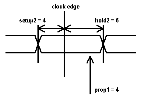
You are debugging a circuit that has two flip-flops in a shift register configuration. Users have detected anomalies in the behavior of the circuit and have asked you to find the problem. The timing characteristics of the two flip-flops are as follows:
The problem is that the propagation time of the first flip-flop is less than the hold time of the second. We are violating the rule that says an input to a flip-flop will not change within a window around the clock edge defined by the setup time and the hold time. In this situation, the input to the second flip-flop (the output of the first) may change before the second FF has a chance to capture the input's value at the clock edge. It will appear as if an input value made it through two FFs in one clock cycle.
(b) How would you correct it while leaving the flip-flops in place and adding only inverters with a propagation delay of 2? (6 points)
The propogation delay of the first FF must be made
to be greater than the hold time of the second FF. This can be accomplished
by adding two inverters in series between the two FFs (slowing down the
output of the first FF on its way to the input of the second FF).
We need two inverters to keep the signal sense the same. Now the
propagation delay will be 4 + 2 + 2 (the original propagation delay plus
the delay of the two inverters) for a total of 8 which is greater than
the second FF's hold time of 6.
(c) What is the smallest clock period that can be used on your corrected circuit that will still guarantee correct operation? Explain. (7 points)
The clock period is defined by the propagation delay
plus the setup time. In other words, the signal has to get from one
FF to the next (propagation time) and get there early enough before the
clock edge (setup time). Therefore, the fastest we can operate our
modified circuit is at a period of 8 + 4 or 12.
5. Finite State Machine Design (25 points)
The circuit below consists of a shift-register (3 bits long) and a synchronous set-reset flip-flop.

(a) Derive a state diagram for the state machine composed of the single set-reset flip-flop. The inputs to this machine are S and R. Assume that the two inputs will never both be 1 simultaneously. (8 points)
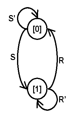
(b) Derive the state table for this
state machine. (7 points)
|
|
|
|
|
|
|
|
|
|
|
|
|
|
|
|
|
|
|
|
|
|
|
|
|
|
|
|
|
|
|
|
|
|
|
|
|
|
|
|
|
|
|
|
|
(c) Re-implement the FSM using a single D flip-flop instead of a S-R flip-flop. Make sure to minimize your expression for D. (5 points)
D = S + R'Q
(d) What does the entire circuit
(1-bit FSM + 3-bit shift-register) do? (5 points)
The circuit is a framer for packets defined by two consecutive 1s. The first set of consecutive 1s sets the FF while the second set resets it. data_valid is high in between the two sets of consecutive 1s. Note that it is also high between packets (after two 1s reset the FF they then set it again two cycles later) making the name data_valid not entirely appropriate. See the example waveforms below.
