
CSE 370 Solution Set #7
Spring 1999
Total Points 20
Problem 1 - 7 points
The Verilog below illustrates some important points.
You should use 2 always blocks: 1 on posedge CLK for changing states, and one on all the important inputs and internal registers for calculating the next state. This makes sense if you think about it from a hardware perspective. The registers are only looking at the data on the posedge CLK, but the next_state functions are combinational, which are always updating their values based on the value of the inputs. No points were deducted, for doing everything in one always block, but it doesn't make sense if you think about how it would be implemented.
It is important not to put any other inputs in the posedge CLK always block. If one of those inputs change then the registers will get a new value, and you no longer have a clock driven state machine.
The verilog below, as well as the rest of the verilog in the answer key, has not been run, so there may be little errors (missing ;. etc.).
Many of you made, or tried to make, your modules chainable. If you did this it requires external logic to do the rotates. If you put the rotation code internally the values will rotate inside each bit slice, instead of around the whole thing. To have a truly chainable component, it cannot know the difference between a shift and a rotate (since it doesn't know whether it's chained or not). You need to feed the appropriate bit in the LeftIn and RightIn inputs, based on the control values are set to. A simple AND gate that takes the Right Out as an input, and a line that goes high whenever Rotate Right is selected as another input will calculate the LeftIn bit. Of course you need a symmetric case for RotateLeft. This is unimportant for this assignment, but may be of interest to some of you.
module ShiftReg8bit(CLK, S2, S1, S0, d7, d6, d5, d4, d3, d2, d1, d0, q0, q1, q2, q3, q4, q5, q6, q7);
 input           CLK;
 input           S2,S1,S0;
 input           d7,d6,d5,d4,d3,d2,d1,d0;
 output          q0,q1,q2,q3,q4,q5,q6,q7;

 reg qO, ql, q2, q3, q4, q5, q6, q7;
 reg[7:0] indata;
 reg[7:01 out;
 reg[7:0] nextout;
 reg[2:0] sel;

assign indata = {d7,d6,d5,d4,d3,d2,dl,d0};
assign sel  = {s2,sl,s0);

// State Definitions
`define  Hold           3'b000
`define  Load           3'b001
`define  Clear          3'b011
`define  Complement     3'b011
`define  ShiftRight     3'b100
`define  RotateRight    3'b101
`define  ShiftLeft      3'b110
`define  RotateLeft     3'b111


/* clock driven "state" transitions */
 always @(posedge CLK) begin
	 out = nextout;
	$display(I,Input  is %b, Sel is %d, Output is %b", indata, sel, out);
 end

/* combinational logic to determine next output */
 always @(out or sel or indata) begin
	case(sel):

	'Hold: 		nextout = out;
	'Load: 		nextout = indata;
 	'Clear: 	nextout = 8'h00;
 	'Complement: 	nextout = ~out;
 	'ShiftRight: 	nextout = {1'b0, out[7:1]};
 	'RotateRight: 	nextout = {out[O], out[7:1]};
 	'ShiftLeft: 	nextout = {out[6:0], 1'b0};
 	'RotateLeft: 	nextout = {out[6:0], out[7]];
	endcase
 end

 assign q7  = out[7];
 assign q6  = out[6];
 assign q5  = out[5];
 assign q4  = out[4];
 assign q3  = out[3];
 assign q2  = out[2];
 assign ql  = out[l];
 assign q0  = out[0];

endmodule
Sample Output (from $Display Statement)
 Input= 11100111, sel= 0, out= 00000000
 Input= 11100111, sel= 0, out= 00000000
 Input= 11100111, sel= 0, out= 00000000
 Input= 11100111, sel= 1, out= 11100111
 Input= 11100111, sel= 1, out= 11100111
 Input= 11100111, sel= 1, out= 11100111
 Input= 11100111, sel= 2, out= 00000000
 Input= 11100111, sel= 2, out= 00000000
 Input= 11100111, sel= 2, out= 00000000
 Input= 11100111, sel= 3, out= 11111111
 Input= 11100111, sel= 3, out= 00000000
 Input= 11100111, sel= 3, out= 11111111
 Input= 11100111, sel= 4, out= 01111111
 Input= 11100111, sel= 4, out= 00111111
 Input= 11100111, sel= 4, out= 00011111
 Input= 11100111, sel= 5, out= 10001111
 Input= 11100111, sel= 5, out= 11000111
 Input= 11100111, sel= 5, out= 11100011
 Input= 11100111, sel= 6, out= 11000110
 Input= 11100111, sel= 6, out= 10001100
 Input= 11100111, sel= 6, out= 00011000
 Input= 11100111, sel= 7, out= 00110000
 Input= 11100111, sel= 7, out= 01100000
 Input= 11100111, sel= 7, out= 11000000
 Input= 11100111, sel= 6, out= 10000000
 Input= 11100111, sel= 6, out= 00000000
 Input= 11100111, sel= 5, out= 00000000
 Input= 11100111, sel= 5, out= 00000000
 Input= 11100111, sel= 4, out= 00000000
 Input= 11100111, sel= 4, out= 00000000
 Input= 11100111, sel= 3, out= 11111111
 Input= 11100111, sel= 3, out= 00000000
 Input= 11100111, sel= 2, out= 00000000
 Input= 11100111, sel= 2, out= 00000000
 Input= 11100111, sel= 1, out= 11100111
 Input= 11100111, sel= 1, out= 11100111
 Input= 11100111, sel= 0, out= 11100111
 Input= 11100111, sel= 0, out= 11100111
Problem #2 - 3 points
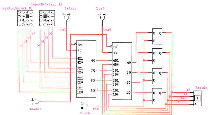
It is not a good idea to play with the clock to stop flip-flops from latching. When you put logic in front of the clock, you delay the signal, and pretty soon all your registers are latching at different times. Clock skew can create some heinous bugs in your circuit. In this implementation you select which input to read with the leftmost mux (controlled by select) and choose whether to send in the values from the registers or the inputs with the second mux (controlled by load).
This is a sample waveform with a good explanation of what going on. All you need to do is tell me what is happening on each clock edge and why. This makes grading a lot easier.
g. 
Problem 3 - 3 points

Here is the verilog, but again it has not been actually compiled, so small syntax errors may exist. Notice again: Two Always Blocks!!! You also should have more comments then this : )
module Register(Select, Load, CLK, Q15, Q14, Q13, Q12, Qll, QIO, Q9, Q8, Q7, Q6, Q5, Q4,
      Q3, Q2, Q1, Q0, AO, Al, A2, A3, A4, AS, A6, A7, A8, A9, AIO, All, A12, A13, A14,
      A15, BO, BI, B2, B3, B4, B5, B6, B7, B8, B9, BIO, Bll, B12, B13, B14, B15);

 input           Select, Load, CLK;
 output          Q15, Q14, Q13, Q12, Qll, QIO, Q9, QB, Q7, Q6, Q5, Q4, Q3, Q2, Ql, QO;
 input           AO, Al, A2, A3, A4, AS, A6, A7, A8, A9, AIO, All, A12, A13, A14,  A15;
 input           BO, BI, B2, B3, B4, B5, B6, B7, B8, B9, B10, Bll, B12, B13,  B14, B15;

 reg  [15:0] state;
 reg  [15:0] next_state;
 reg  [15:0] inputa;
 reg  [15:0] inputb;

 assign   state  = {Q15, Q14, Q13, Q12, Q11, Q10, Q9, Q8, Q7, Q6, Q5, Q4, Q3, Q2, Q1, Q0};
 assign   inputa = {AI5, A14, A13, A12, A11, A10, A9, A8, A7, A6, A5, A4, A3, A2, Al, AO};
 assign   inputb = {BI5, B14, B13, B12, B11, B10, B9, B8, B7, B6, B5, B4, B3, B2, B1, B0};

 always @(posedge CLK) begin
	state[15:0] = next_state[15:0];
	$display("Clock: %h Load: %h Select: %h Input A: %h Input B: % h Output: %h",
		  CLK, Load, Select, inputa, inputb, state);
 end


 always @(Load or inputa or inputb or Select) begin
 	if (Load == 1'b1)
 		if (Select == 1'b1) next_state[15:0] = inputA[15:0];
		else 		    next_state[15:0] = inputB[15:0];
 end

 assign   Q15 = state[I5];
 assign   Q14 = state[14];
 assign   Q13 = state[13];
 assign   Q12 = state[12];
 assign   Q11 = state[11];
 assign   Q10 = state[10];
 assign   Q9  = state[9];
 assign   Q8  = state[8];
 assign   Q7  = state[7];
 assign   Q6  = state[6];
 assign   Q5  = state[5];
 assign   Q4  = state[4];
 assign   Q3  = state[3];
 assign   Q2  = state[2];
 assign   Ql  = state[l];
 assign   Q0  = state[0];

endmodule
And here is a sample test vector. You should add notes to your test vector just like the wave forms (unlike this one).
 Clock:  1  Load:  0   Select:  0  Input  A: dead   Input B:  beef   Output:  xxxx
 Clock:  1  Load:  0   Select:  0  Input  A: dead   Input B:  beef   Output:  xxxx
 Clock:  1  Load:  0   Select:  1  Input  A: dead   Input B:  beef   Output:  xxxx
 Clock:  1  Load:  0   Select:  1  Input  A: dead   Input B:  beef   Output:  xxxx
 Clock:  1  Load:  1   Select:  1  Input  A: dead   Input B:  beef   Output:  dead
 Clock:  1  Load:  1   Select:  1  Input  A: dead   Input B:  beef   Output:  dead
 Clock:  1  Load:  1   Select:  0  Input  A: dead   Input B:  beef   Output:  beef
 Clock:  1  Load:  1   Select:  0  Input  A: dead   Input B:  beef   Outpur:  beef
 Clock:  1  Load:  0   Select:  0  Input  A: dead   Input B:  beef   Output:  beef
 Clock:  1  Load:  0   Select:  0  Input  A: dead   Input B:  beef   Output:  beef
 Clock:  1  Load:  0   Select:  0  Input  A: beef   Input B:  dead   Output:  beef
 Clock:  1  Load:  0   Select:  0  Input  A: beef   Input B:  dead   Output:  beef
 Clock:  1  Load:  1   Select:  0  Input  A: beef   Input B:  dead   Output:  dead
 Clock:  1  Load:  1   Select:  0  Input  A: beef   Input B:  dead   Output:  dead
 Clock:  1  Load:  1   Select:  1  Input  A: beef   Input B:  dead   Output:  beef
 Clock:  1  Load:  1   Select:  1  Input  A: beef   Input B:  dead   Output:  beef
 Clock:  1  Load:  0   Select:  1  Input  A: beef   Input B:  dead   Output:  beef
 Clock:  1  Load:  0   Select:  1  Input  A: beef   Input B.  dead   Output:  beef
Problem 4 - 7 points

Gray Code Counter. Again, verilog was copied and may have
small syntactic errors, but the overall form is correct. Putting the reset in you
posedge CLK always block saves some keystrokes in the other always block. Note
that nowhere do I use any sequential assignment (i.e. assigning next_state, then
re-assigning it later in the same block of code). How would this be accomplished in
hardware? It wouldn't!!! hardware is inherently parallel. You should only
assign to a given variable one per execution of an always block.
 module gray_code-counter(enable, reset, CLK, out0, outl, out2);

 input enable, reset, CLK; output out0, outl, out2;

/* internal registers */
 reg [2:0] state;
 reg [2:0] next_state;

/* clock driven state registers - easy place for reset */
 always @(posedge CLK) begin
	if(reset) state = 3'b110;
	else 	  state = next_state;

	$display("out= %h, state= %h, reset= %b, enable= %b", out, state, reset, enable);
 end

/* combinational logic */
 always @(enable or state) begin
	if(enable) begin
		case (state)
		3'b000: next_state = 3'b001;
		3'b001: next_state = 3'b011;
		3'b011: next_state = 3'b010;
		3'b010: next_state = 3'b110;
		3'b110: next_state = 3'b111;
		3'b111: next_state = 3'b101;
		3'b101: next_state = 3'b100;
		3'b100: next_state = 3'b000;
	 endcase
	end

	else next_state = state;
 end

/* output assignments */
 assign out2 = state[2];
 assign out1 = state[1];
 assign out0 = state[0];

endmodule
Test Output - Note the $display is in the posedge CLK always, giving one output per cycle. This is good.
out= 000 state= 000 reset= 0 enable= 0
out= 000 state= 110 reset= 1 enable= 0
out= 110 state= 110 reset= 1 enable= 0
out= 110 state= 110 reset= 0 enable= 0
out= 110 state= 110 reset= 0 enable= 0
out= 110 state= 111 reset= 0 enable= 1
out= 111 state= 101 reset= 0 enable= 1
out= 101 state= 100 reset= 0 enable= 1
out= 100 state= 000 reset= 0 enable= 1
out= 000 state= 001 reset= 0 enable= 1
out= 001 state= 011 reset= 0 enable= 1
out= 0ll state= 010 reset= 0 enable= 1
out= 010 state= 110 reset= 0 enable= 1
out= 110 state= 111 reset= 0 enable= 1
out= 111 state= 101 reset= 0 enable= 1
out= 101 state= 110 reset= 1 enable= 1
out= 110 state= 110 reset= 1 enable= 1
out= 110 state= 111 reset= 0 enable= 1
out= 111 state= 101 reset= 0 enable= 1