In Synario, simulating a schematic or ABEL design is a 2-step process composed of: (1) writing a Verilog Test Fixture telling Synario how we want our design to be tested, and (2) executing that Test Fixture via the Functional Simlator.
Using the Simulator is much like the debugging process used with programming languages; whereas in the first case we step line-by-line through the code monitoring the values of variables in a numeric display, with the Simulator we step by time increments through the Test Fixture as we graphically monitor the values of the inputs, outputs, and internal signals of our design using the Simulator's Waveform Viewer. Hence simulation let's us validate our design by checking our inputs against the outputs.
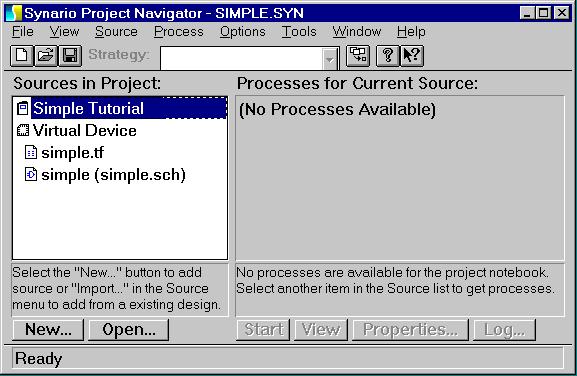
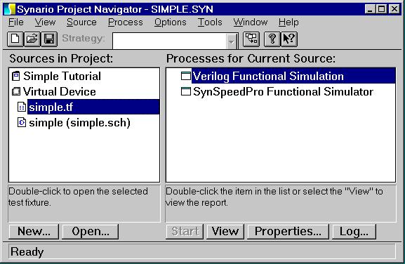
In the Project Navigator, begin by left-clicking on the "simple.tf" Test Fixture in the "Sources in Project:" window pane.
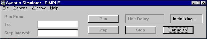
Now left-double-click on "Verilog Functional Simulation". First a status window with the message "Synario Process - Updating: Verilog Functional Simulation" will appear. After Synario finishes updating files, the actual Functional Simulator window will appear. Note the status box in the upper-right hand corner of the window; it should flash this series of messages: "Starting ..", "Reset OK", "Opening .." "Initializing ..", "Busy .." and finally "Ready". If either of the messages "Failed!" or "Died?!" appear, this indicates an error has occurred. To get more information on what happened, execute "View Log File" in the "File" menu, which usually will tell you what went wrong.
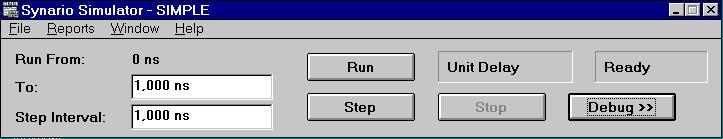
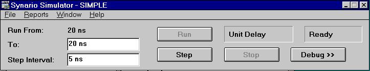
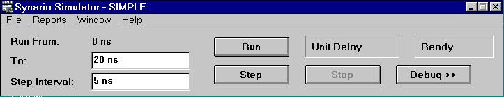
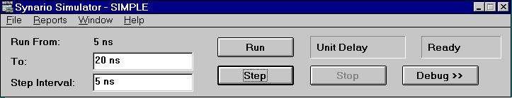
In the upper-left hand corner of the window we will see the text "Run From:"; this tells us how far we are into the simulation. At this point we have not yet begun simulating, so the time reads "0 ns" to indicate that no time has elapsed. Below this is the text "To:", which asks us how long we want the simulation to run. Looking back at our Test Fixture we see that 20 ns should allow enough time for our final change of inputs to propagate through to the outputs, so we will enter "20 ns" in this window pane. Below this is the text "Step Interval:", which asks us for the time increment we want to use to step through our Test Fixture. Looking back at our Test Fixture once more, we see that we used 5 ns interval between input changes, so we will enter "5 ns" here as our step interval.
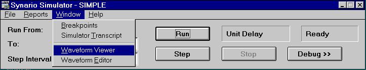
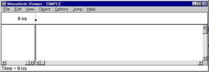
Next we need to open the Waveform Viewer window. This is accomplished by selecting "Waveform Viewer" from the "Window" menu. Although we are not going to do anything with the Waveform Viewer quite yet, the window must be open before we can perform our next step.
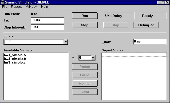
Next we will add the inputs, outputs, and internal signals of our design that we wish to monitor to the Wavefrom Viewer. To accomplish this, go back to the Simulator window and click on the "Debug >>" button. The window will now expand to look like this:
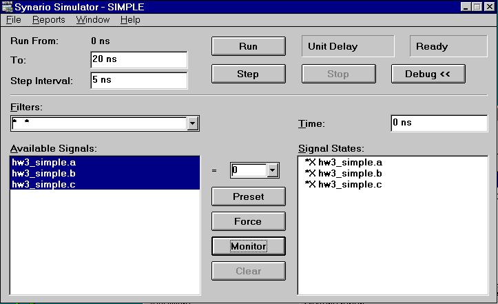
To add the signals to the Waveform Viewer, we simply select the names of the signals we want to monitor from the "Availiable Signals" window pane and click on the "Monitor" button. We can see below that all of the signals have been added to the "Signal States" window pane, meaning they are now being monitored. Note the "*X" to the left of each signal name, indicating that the signals' values are undefined at the current state of the simulation given in the "Time:" window pane above. Because we have not yet begun the simulation, as the time of "0 ns" indicates, it makes sense that signal values should be undefined. Now that our signals are being monitored we can go ahead and click on the "Debug <<" button once more to re-hide this portion of the window.
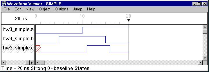
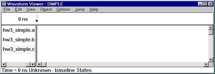
Turning our attention back to the Waveform Viewer, we can see that all of our signals have, in fact, been added to the Viewer. Try selecting one of the signals by clicking on its name with the left mouse button. Note that the text at the bottom of the window tells us the current state of the simulation, 0 ns, and that the value of the selected signal is "Unknown", reaffirming what we already know about all signals being initially undefined.
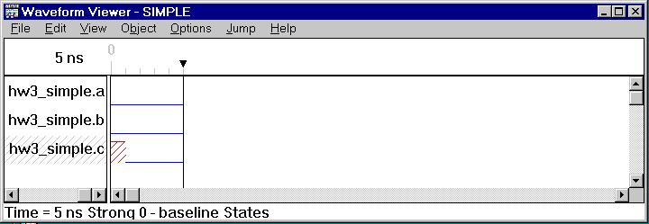
We are now ready to begin simulating our design for the simple AND gate. Click on "Step" in the Simulator window to simulate the first 5 ns of our Test Fixture and note that several things happen. In the Simulator window, "Run From:" changes to 5 ns to indicate that the current state of our simulation is now time = 5 ns. As for the Waveform Viewer window, we can see that all of the signal states are now displayed graphically for 0 - 5 ns. Signals "a" and "b" are shown to both be 0, which is what we expect since that was the value the Test Fixture assigned to them at time = 0 ns and has made no new assignment to them since then. Signal "c", on the other hand, remains undefined (indicated by diagonal red stripes) for 1 ns before settling down to the expected 0 (0 * 0 = 0). This can be understood when we consider that in the Test Fixture we set the propagation delay per gate to 1 ns, and since our inputs pass through 1 gate before reaching the output, we should expect a time delay of 1 ns per gate * 1 gate = 1 ns between our change in inputs and the resulting change in output.
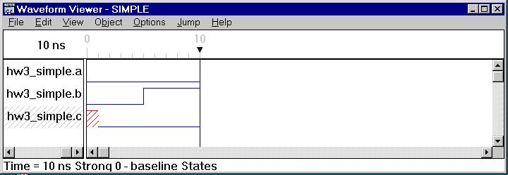
Now let's hit the "step" button one more time. In the Simulator window, it now reads "Run From: 10 ns" to show we are now 5 more ns into our simulation. In the Waveform Viewer, see how the value of the input B has rose to 1 at time = 5 ns. This is what we assigned it to do in the test fixture, and we have now simulated (0 * 1 = 0).

Let's now go ahead and finish up our simulation; hitting the "Run" button will execute the Test Fixture up until the time we've specified in the "To:" window pane, 20 ns. Between time = 10 ns and time = 15 ns we simulated the case (1 * 1 = 1) and between time = 15 ns and time = 20 ns we simulated the last case (1 * 0 = 0). Notice again that each time the signal "c" changes value, it occurs 1 ns after the change in inputs; the propogation delay we discussed earlier.