Launch Maya
In a Unix Shell window type: maya& (The ampersand is so you can keep working in the shell window)
- Create a new project.
You will create a new project in this step. Maya creates directory structures for each project so that files can be found easily.
1. Select File->Project->New...
2. Type "temple" as the new project name. Click on Use Defaults at the bottom of the new project window. Click Accept to accept the changes.
You have just created a new project and are now ready to start working in it.
Tip:
It is a good idea to start your projects with four windows so you
can see your work from all points of view. If your window setup does not
show four windows choose: Window->Saved Layouts->Four View.
Building the Base of the Temple
This temple is built from the ground up. The base is constructed first, with a cube primitive that is scaled and moved into place.
- Create a cube and name it.
1. Select "Modeling" from the pop-up menu found at the left of the status bar, or press F3 to switch to the Modeling menu set.
2. Select Primitives->Create NURBS->Cube. The Cube is automatically created at (0, 0, 0).
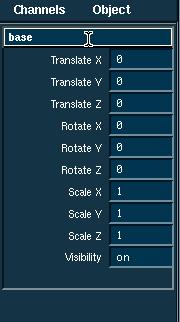
3. This will eventually be the base of the temple. Rename this object "base" by clicking where it says "nurbsCube" in the Channel Box on the right hand side of the screen. Change this so that it reads "base".
- Scale the Cube with the mouse.
3. Select Modify->Transformation Tools->Scale Tool. A Scale manipulator will appear over the cube.
Tip: You can use the shortcut keys: 'W','E','R' to activate the "Translate", "Rotate", and "Scale" commands, respectively.
4. Using the grid as a guide, scale the cube until it is about 8 units wide (in the X direction) by 16 units long (in the Z direction). To scale in the X direction, click and drag the red square on the scale manipulator, click and drag the blue square to scale in Z.
- Scale the height of the cube.
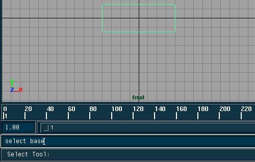
5. Click in the viewport labeled 'front' to activate it.
6. The base was probably deselected when you activated the Front window, type "select base" on the command line at the bottom of the Maya window. This will reselect the base of the temple. Remember this, as you will want to use this method to reselect objects when they become deselected.
Note: NURBS cubes in maya are made up of faces, if you attempt to select the cube by click-dragging a window around the cube, you will select the faces of the cube, and not the actual cube node itself (ask about "grouping" if you're confused).
7. Click and drag the Green square on the scale manipulator to scale the base to a height of about 3 units in Y.
- Rescale the cube accurately using absolute values.
8. To scale the base to the exact proportions, go to the channel box and change the values of "Scale x", "Scale y", and "Scale z" to 8, 3, and 16, respectively.
You now know how to manipulate an object using both mouse movements and keyboard input. You can also use either method to move the base.
Moving the Base.
- Move the cube with the mouse.
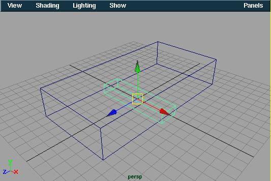
1. With the base selected, select Modify->Transformation Tools->Move Tool (Or press 'W').
2. In the Front Viewport, click-drag the green manipulator arrow to move the base up along the Y axis so that the bottom of the base sits on the "ground surface" (This is the 2D grid displayed, a.k.a the XZ plane).
- Placing the cube using the Channel box.
3. To move the base to the exact location, go the the channel box and change the value of "Translate y" to 1.5.
- Tumble and Dolly the Perspective view
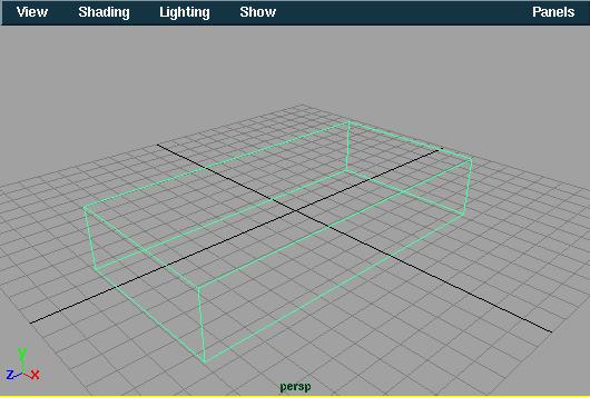
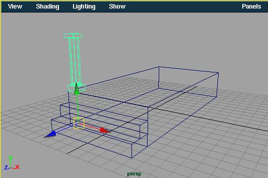
4. In the Perspective Viewport, select View->Camera Tools->Tumble Tool and View->Camera Tools->Dolly Tool to tumble and dolly the view so that it looks something like the figure below.
Tip: For more convenient access to the camera tools, you can use shortcut keys. Hold down the <Alt> key and using different combinations of the mouse buttons, you can use each of the camera tools.
To Track: Hold down <Alt> and Click-drag with the middle mouse button.
To Tumble: Hold down <Alt> and click-drag with the left mouse button.
To Dolly: Hold down <Alt> and click-drag with both the left and middle mouse buttons.
These are VERY useful shortcuts and will save you alot of time in future projects. Try to make good use of them.
- Create the bottom step of the temple.
1. Select Primitives->Create NURBS->Cube. Rename this cube "bottomStep" using the same method as used to rename the base.
2. Scale this cube by 8 in the X direction and 2 in the Z direction.
- Move the step to its proper position using grid snapping.
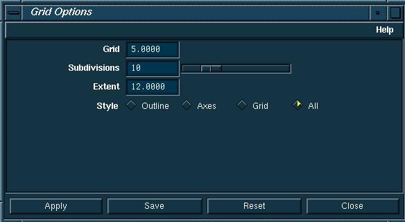
3. The grid spacing is too large to move our step into the right position. To change the grid spacing select Display->Grid *. Change the number of subdivisions to 10. Click Apply to apply your changes, then click Close.
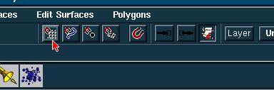
4. Turn on the Snap to Grid option using the icon on the toolbar.
Tip: To use grid snapping, you can also hold down "X" while manipulating objects.
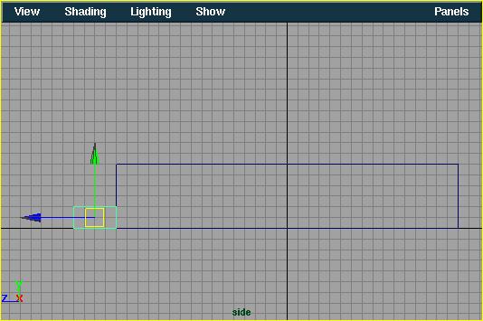
5. In the Side Viewport, move the bottom step so that it sits exactly in front of the temple base.
6. Turn off grid snapping by clicking on the same icon you used to turn it on.
- Create the middle step of the temple.
7. Create another cube and name it "middleStep".
8. If it isn't already, select the move tool while the middle step is selected.
9. Hold down the "X" key to temporarily turn on grid snapping, and move the cube just above the bottom step in the Side Viewport.
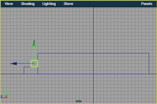
Notice that releasing the "X" key turns off grid snapping.
10. Scale the middle step by 8 in the X direction.
Note: Grid snapping does not work for the scale tool, you will want to use the Channel box to scale this correctly.
- Template the existing geometry
11. Templating the geometry allows you to work without accidentally altering your work up to this point. Select Edit->Select All to select all the geometry in the scene.
12. Select Display->Object Components->Templates to template all the objects in your scene.
- Reset the Grid spacing
13. Select Display->Grid* and change the subdivision setting back to 5.
- Save your work.
Be sure to save your work at regular intervals, often you will want to save multiple versions of your work as you progress.
1. Select File->Save Scene as...
2. You will see the complete path where your file will be saved near the bottom of the window. Type "temple_01" after the path and click Save to save your scene.
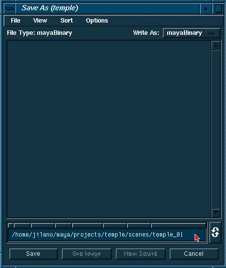
Your scene has been saved in a directory called "scenes", which is a subdirectory of the project directory which is called "temple" (or whatever you named it at the beginning of the lesson).
Building the columns of the temple.
- Using Absolute and Relative Values
As you build the column, you will also learn about the difference between Absolute and Relative values.
- Build the column pedestal
1. Create a cube and name it "pedestal".
2. Move the cube 3.25 units in the Y direction.
3. Scale the cube by 0.5 in the Y direction. Your cube should be sitting right on top and center of the base of the temple.
- Create the column base using a half sphere.
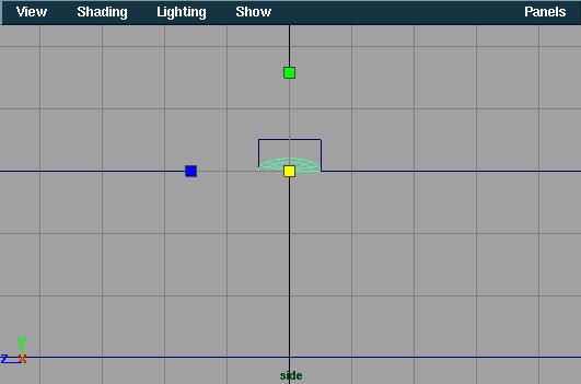
4. Select Primitives->Create NURBS->Sphere *. In the Sphere dialog box: Press 'Reset', change the Axis to "X", the Start sweep angle to 180 and the radius to 0.5. Click Create to create the half-sphere. Close the dialog box. Name this object "columnBase".
5. Using grid snapping, move the sphere to the same position as the column pedestal in the Side Viewport. You may want to track and dolly the Side Viewport to get a better look at the objects.
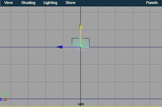
6. Reposition the sphere in absolute mode. With the sphere still selected, select the move tool. Click on the coordinate input box
and type 0 0.5 0 to move the sphere on top of the column pedestal.
Note: The coordinate input box can be used to enter exact values for transformations. After selecting a transform tool, you can enter values here separated by a space to change the transform values. To enter a value to transform along a single axis, first select the manipulator handle for that axis, then enter the desired value in the coordinate input box.
Oops! The column base has moved towards the ground. Because you were in Absolute mode, the sphere moved to the coordinates (0,0.5,0).
- Undo the last transformation
7. Select Edit->Undo. The sphere returns to its previous position.
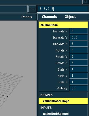
- Reposition the sphere using relative values.
8. Click on the abs/rel toggle next to the coordinate input box. This will put you in Relative mode.
9. With the sphere and move tool still selected, type 0 0.5 0 in the coordinate input box.
The sphere moves above the pedestal. 0.5 units in the Y direction, relative to its previous position.
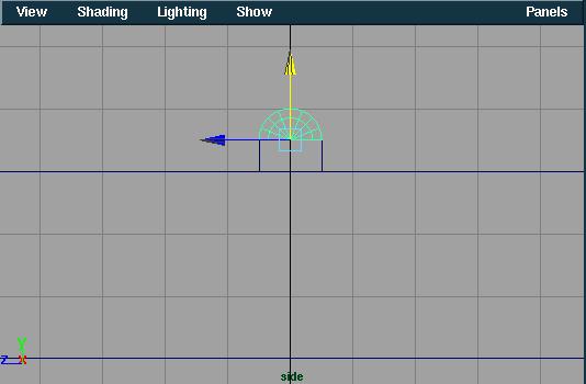
- Scale the sphere using relative values.
10. With the sphere still selected, select the scale tool.
11. In the coordinate input box, type 1 0.4 1. This will scale the sphere 0.4 in the Y direction relative to its existing dimensions.
Moving the pivot
The main body of the column is created with a cylinder. By default, pivot points of primitives lie at their centers. By moving the pivot, you can change how the cylinder scales.
- Build a cylinder.
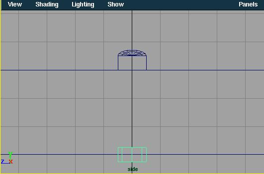
1. Select Primitives->Create NURBS->Cylinder *. In the Cylinder Dialog box, change the End sweep to 360, the Axis of the cylinder to Y, and the radius to 0.5. Click Create to create the cylinder. Close the dialog box. Name this cylinder "columnBody".
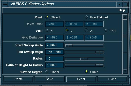
This will create a cylinder that is correctly oriented to the base of the temple.
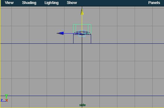
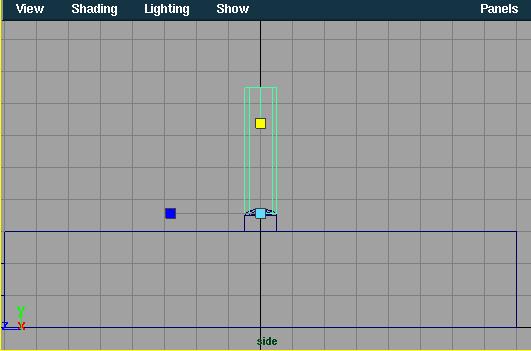
- Move the pivot point so that it is at the bottom of the cylinder.
1. With the Cylinder and Move Tool (or any transform tool) selected, press the <insert> key. This will change the manipulator into a pivot manipulator. In the coordinate input box, type 0 -0.25 0 to place the pivot at the bottom of the cylinder.
2. Press <insert> again to switch to the Move Tool. Move the cylinder along the Y axis until it sits on top of the column's base and intersects the half sphere.
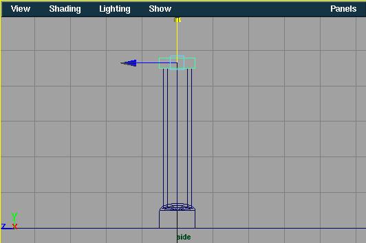
- Scale the cylinder based on the new pivot point.
3. With the cylinder selected, select the Scale Tool. Scale the cylinder in the Y direction to a height of about 4 units.
- Scale the width of the cylinder.
4. With the scale tool still selected, scale the cylinder in relative mode by typing 0.8 1 0.8 in the coordinate input box.
By staying in Relative mode, you can preserve the column height while scaling other dimensions with the keyboard input. The same input in Absolute mode would change the column's height to 1 unit.
Copying an existing object.
You can copy the base of the column to create the top part. Copying and modifying existing geometry is often easier than creating new primitives and having to redo the same transformations.
- Pick and copy the column pedestal.
1. Select the base of the column by typing "select pedestal" on the command line. (Remember this from the beginning of the tutorial? You can see how important it is to name your objects as you work.)
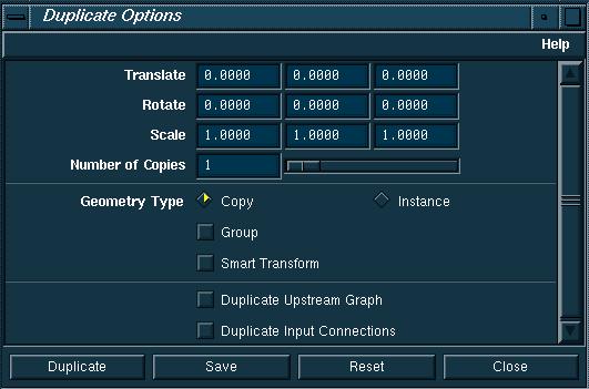
2. From the Edit menu, select Duplicate*. The Duplicate options box appears. Click on the Reset button to make sure that the Translate, Rotate, and Scale factors are set to their defaults. Click "Duplicate" to make a single copy of the selected piece. Close the dialog box. Name this object "columnTop".
- Scale and move the duplicated object
3. The duplicated cube currently sits on the original. Select the Scale tool. Switch to Absolute mode by clicking on the Abs/Rel button next to the coordinate input box and type 1 0.3 1 in the coordinate input box and press <enter>.
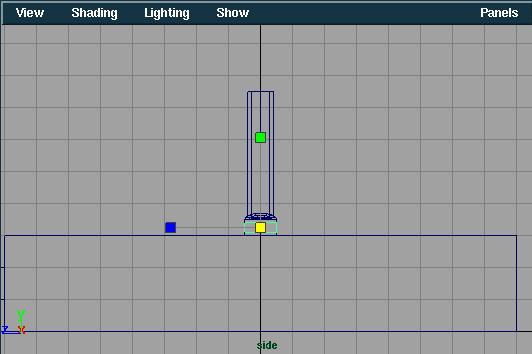
4. Move the new cube to along the Y axis until it sits on top of the cylinder. The column is complete, although the pieces are not connected. The next step is to group the pieces into a single object.
Grouping the primitives.
Once grouped, the individual objects are placed under a new node that can be copied and moved as a single object. Grouping objects is an essential modeling technique. It is also an efficient way to structure and control your geometry.
- Select and group all pieces of the column.
1. Type "select pedestal columnBase columnBody columnTop" on the command line to select all the column pieces.
2. From the Edit menu, select Group to group the objects as one. Name this group "Column"
3. The group now displays a single pivot point at the origin. The pivot point is at a height of 0 even thought the column sits 3 units above the ground. This means you won't have to alter the Y translation when you move the grouped object to its proper position.
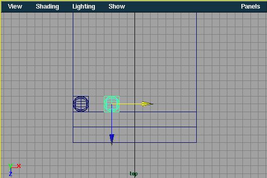
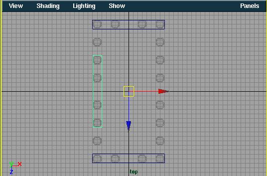
4. Select the Move Tool and type -3.5 0 7.5 in the coordinate input box to position the column at the corner of the temple base.
Copying a Column
By copying this column, you can create the other temple columns. The first copy is positioned with grid snap. After half of the columns have been built, you can use mirroring to complete the rest.
1. Select Display->Grid *. Change the number of subdivisions to 10. Turn on grid snapping.
- Copy and move the column.
2. From the Edit menu, select Duplicate. This creates a single copy of the column and places it on top of the original.
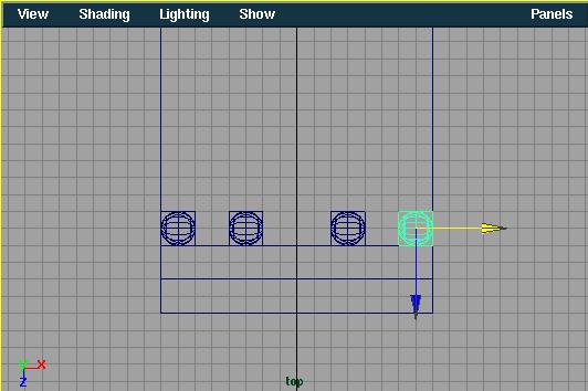
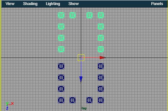
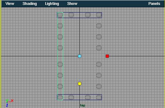
3. In the Top Viewport, move this new column 2 units (or 4 grid spaces) to the right. You may want to Dolly and Track the Top viewport to make this easier.
4. Duplicate this column and move it 3 units to the right. Repeat this step to make a fourth column and move it another 2 units to the right.
- Make multiple copies of the end columns.
Now we will examine a new way of selecting objects. Up until this point, you have been selecting individual objects within groups (a cube is actually a group of faces). Notice that if you click on a part of a column, only the piece of the column will be selected. You want to be able to click on a column and select the entire group.
- Change the Select mode to "Select by heirarchy and combinations".
1. Click on the "Select by heirarchy" button on the toolbar.
![]()
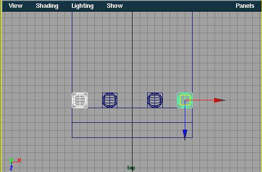
2. Click on a column, notice that the entire column is selected.
Note: You could have worked in this mode since the beginning, but now you have been through a good introduction to understanding grouping and heirarchy ("Thanks alot."). Try creating a cube and selecting it with the mouse now. Notice that the entire cube is selected instead of just a face.
3. Click on the first column and hold down <shift> and click on the fourth column to add that column to the selection.
4. Select Edit->Duplicate *. In the dialog box change the translate values to 0 0 -2. Type "3" for the number of copies value. Click Duplicate. The end columns are each copied three times along the sides of the temple.
- Pick and group all columns.
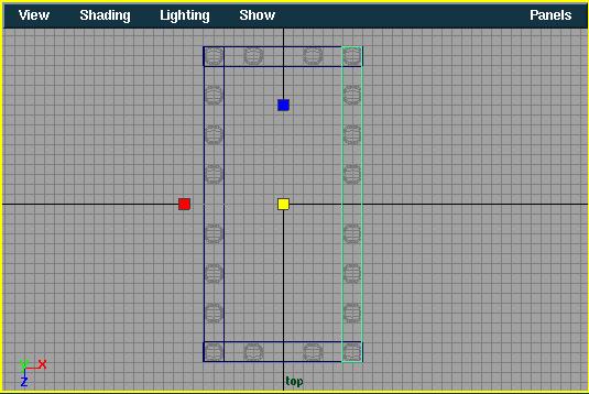
5. In the top window, click and drag a box around the columns to make them active.
6. From the Edit menu, select Group to create a single pivot point at the origin for this group. This pivot point will be used to mirror the objects around the origin.
Note: You must group the columns. If you don't, the columns mirror around their existing pivot points, placing them on top of the original columns.
- Mirror copy the picked columns.
7. From the Edit menu, select Duplicate *. In the Dialog
box, click Reset to return values back to their defaults. Type scale
values of 1 1 -1. Click Duplicate to mirror the copies along
the Z axis. Close the dialog box.
Note: The temple columns were created using the Duplicate function. This function can create single copies or transformed (moved, scaled, rotated) multiple copies. Notice how the columns were first grouped to set the pivot point at the origin.
- Template the columns.
8. Select all the columns and from the Display menu, select Object Components->Templates.
Creating the Entablature
The next part of the temple is the box-like structure supported by the columns. You will create cubes, rotate, mirror, and scale them into place.
- Create and scale a cube primitive.
1. Create a cube. Scale the cube by 8 in the X direction.
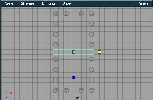
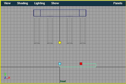
- Position the first piece of the entablature.
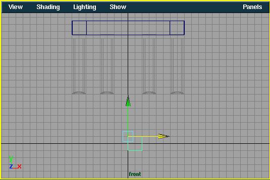
2. Turn off grid snapping and move the cube in the Front Viewport until it sits above the columns.
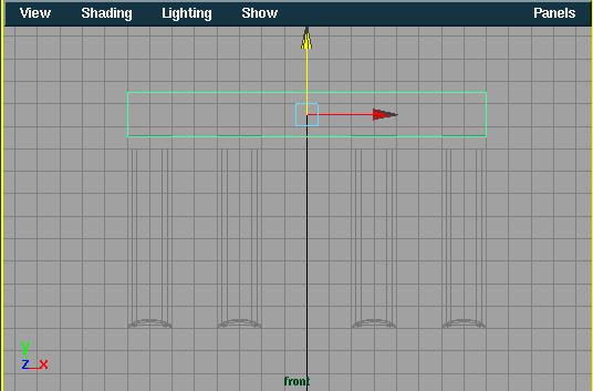
3. In the Side Viewport, move the cube until it lines up with the columns at the far left. Don't forget to dolly and track to make these operations easier.
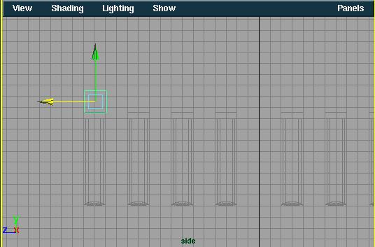
Tip: When positioning objects in 3D space, you should refer to at least two windows.
- Change the cube's pivot point and mirror copy it.
4. Group the cube to itself to change its pivot point. From the Edit menu, select Group while the cube is selected. Notice that the pivot point is now at the origin.
5. Duplicate this cube using the same settings you used for mirroring the columns.
- Copy and rotate the second cube to create the sides of the entablature.
6. While the second cube is selected, from the Edit menu, select Duplicate *. In the option box, click on Reset. Type in Rotate values of 0 90 0. Click Duplicate to create the side of the entablature. Close the Dialog box.
- Move the rotated cube.
7. Move the new cube in the Top or Front viewport along the X axis until it sits above the side row of columns. Notice that the pivot point has moved. Group the cube to itself to place the pivot at the origin.
- Scale the cube's length.
8. The cube is too short. To correct this, scale the cube along the Z axis until the cube touches both ends of the other beams.
- Rotate-copy the third cube.
9. From the Edit menu, select Duplicate *. In the dialog box, change the Rotate values to 0 180 0. Click Duplicate. Close the dialog box.
Your Top Viewport should now look something like this:
Creating the Roof of the temple.
The final part of the temple is the roof. You will again use a cube.
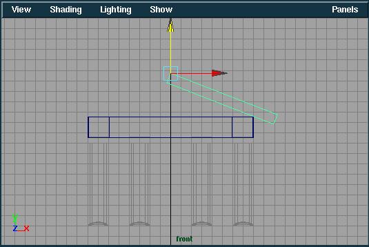
- Create a Cube and move the pivot point.
1. Create a cube. Select the Move tool and press <insert> to switch to the pivot manipulator. Type "-0.5 0.5 0" in the coordinate input box to set the pivot to the upper-front-left corner of the cube.
2. Switch back to the Move tool (press <insert>) Move the cube 0.5 units along the X axis.
3. Select the Scale Tool. In the Front Viewport, scale the cube along the X axis past the edge of the temple by about 3 grid squares.
4. Scale the cube along the Y axis down to a height of about 1 grid square.
5. In the Top viewport, scale the cube along the Z axis until it extends about 1 grid square beyond both ends of the temple.
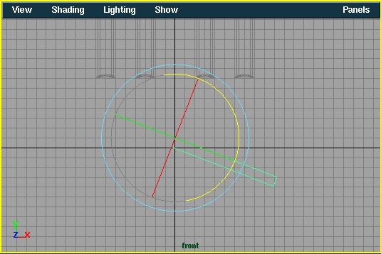
- Rotate the slab around its new pivot point.
5. Select the Rotate Tool. Rotate the slab around the Z axis by click dragging the blue handle of the Rotate manipulator until the cube is oriented something like this:
6. In the Front Viewport, move the cube along the Y axis to the top of the temple.
- Copy-rotate the slab to the other side of the temple.
7. From the Edit menu, select Duplicate. The roof slab will be "mirrored" just like the entablature beam created earlier.
View the temple shaded.
You may want to view the temple as something other than a wireframe. You must untemplate the templates, and change the view to a smooth shaded view.
- Untemplate the geometry
1. Click the "Select by heirarchy: Template" button on the toolbar to select the templates.
![]()
2. Click drag a box around the templates to select them all. From the Display menu, select Object Components->Templates to untemplate these objects.
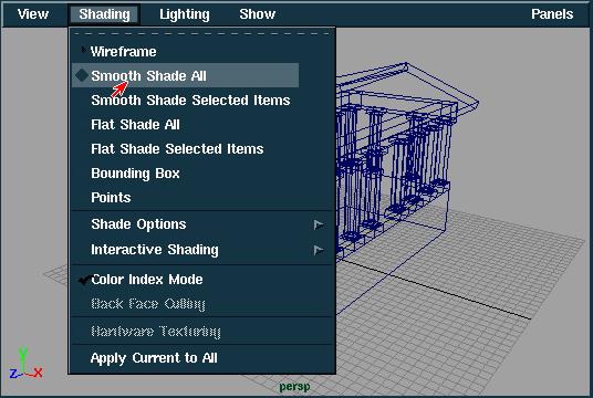
- Change the perspective viewport to Smooth Shaded.
3. In the Perspective viewport select Shading->Smooth Shade All.
Conclusion.
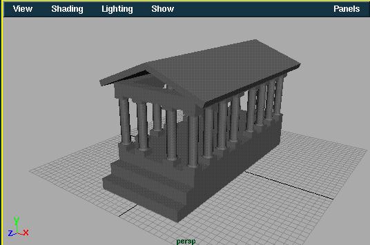
Congratulations! You have just completed your first modeling project in Maya. Try Tumbling, Dollying, and Tracking the perspective viewport to get a better look at your model. In this lesson, you have learned how to:
- Create primitives
- Transform objects
- Set an object's pivot point
- Use keyboard or mouse input to transform objects
- Use the grid as a tool
- Create single and multiple copies of existing objects
Don't forget to save your work!