The goal of this lab is to interface your microcontroll with a computer using SPI and USB. We will also learn how to build a heartrate monitor. In this lab you will learn the following:
1. Do
not plug more than one DLP2232M into a computer. To make sure the drivers
worked properly on the lab image all of the DLP2232M have been setup with the
same serial number. This ensures that windows will recognize the device and
will automatically load the correct drivers. However this causes a problem as
windows seems to have problems with two active USB devices that have the same
serial number.
2. DO
NOT CONNECT POWER directly to the DLP2232M.
It will get its power from its USB connection.
3. Do not run the PC-side applications we give you from your Z: drive. The .NET applications must be run from a local drive (C:) or you will get JIT compilation errors.
1) Take this lab step by step and test along the way to make sure you understand your code and verify that it is working as you expected. Coding the entire project then trying to debug a problem can be challenging. Make sure to test pieces of the assignment one at a time and convince yourself that they are working before moving on to another piece.
2) Utilize the tri-color LED and JTAG for debugging. WARNING: If you update the tri-color LED each time through your main loop you might not be able to see individual color changes because they will be changing too rapidly.
3) Focus on making your system have a reasonable interface. Do not get stuck trying to make timing calculations work out perfectly. The heart rate monitor is inherently noisy. The important thing is to create an interface that “feels” right to a human. People will not notice timing errors of microseconds (maybe not even a few milliseconds depending on where it is in the code).
4) Make sure to think carefully about what data needs to be exchanged over the SPI bus between your microcontroller and the FTDI chip. Since data moves in both directions, deciding on a data packet format for each direction can ensure you get all the data you need on both sides in one transaction.
Brief introduction to AVR Programming
avr-gcc manual – located at: C:\WinAVR\doc\avr-libc\avr-libc-user-manual-1.4.4.pdf
Application notes section for the AVR 8-bit RISC family
Light to Frequency Converter Datasheet
PART 1:
1. Add the USB interface to your breadboard. IMPORTANT: The USB board is preconfigured to gets it power from the USB port so DO NOT attach the USB interface to the 5V power supply of your breadboard. Refer to Figure 8a on page 14 of the DLP Design DLP-2232M datasheet to see how to wire up your USB Bus Powered device.
2. Disconnect the 7-segment LED attached to Port B. Attach your USB interface board as follows:
Refer to page 2 of the ATmega16 datasheet and page 10 of the DLP Design DLP-2232M datasheet to determine the pin numbers.
3. Download the sample SPI/USB code for the PC (files
needed). You should only need to modify SPI-USB.cpp for Part 1. FTDI466API
was created to abstract away setup and DLL details. The sample code will
configure the USB device to act as an SPI master and send bytes using SPI
protocol. The clock rate of the transmission is initially set to 200kHz and
with a latency timer of 5ms (not exposed outside of FTDI466API) that will cause
the USB chip to flush information to the buffers. The latency timer bounds the
amount of time your code has to wait to receive information back from the USB
chip. Refer to the FTDI Chip Application
Note AN2232C-01 for information about the byte commands being issued in the sample
SPI/USB program. NOTE: The command byte 0x35 sends and receives bytes. It
clocks data bytes out on the falling edge of the clock and clocks data bytes in
on the falling edge of the clock.
4. Download connection-check.hex and load it onto your Atmega chip. Run it in conjunction with the SPI/USB code provided. Remember you need to run the .exe file on the C: drive for it to run properly. For every byte sent to the Atmega chip, a byte is recieved, which starts at 0 and is incremented by 1 for each transmission. Change the PC side byte values and the returned values will change as well. Once you have verified that you wired up the connection between the PC and your board, continue on to the next steps.
Question 1: How many ATmega16 cycles
theoretically should occur between received SPI bytes? Assume the SPI is
sending bytes continuously.
Question 2: What command byte would you use
to only send information on the negative clock edge (not receive anything at
the same time)? What command byte would you use to only receive information on
the negative clock edge (not send anything at the same time)? (Hint: refer to
the FT2232C Application Note AN2232C-01)
5. Now
that you have the hardware wired up correctly, you can implement SPI slave
functionality for your ATmega16, refer to the datasheet. Test your code
using the provided sample SPI/USB code. Verify your SPI slave code is working
by displaying the low 3 bits of the last byte sent by the PC in
binary on your tri-color LED (e.g. if red=high bit, green=middle bit, blue=low
bit then 0 = off, 1 = blue, 2 = green, etc) and by sending bytes
back to the PC over the SPI.
NOTE: The datasheet states: "The Slave may continue
to place new data to be sent into the SPDR before reading the incoming
data" It also states: " The system is
single buffered in the transmit direction and double buffered in the receive
direction" This single buffer can cause a problem if the master is
constantly sending bytes and your program does not update the SPDR in time
before the next shift sends (while the send is occurring you cannot update the
buffer). Some groups will not experience this problem because they designed
their program so that they are updating SPDR fast enough. Others will have a
problem because their protocol does not cause them to send a byte in the middle
of packet. You will need to be able to consistently update the value to the
SPDR at the right time to send the data.
PART 2:
1. For this portion of the lab you will develop two applications, one each for the Atmel microprocessor and your PC. The application on your microcontroller should determine the period from your heartrate monitor and continually send that via the SPI to the 2nd program running on the PC. The program running on the PC should take that data from the microcontroller and determine the heartrate in terms of beats/second. The PC application should then send the calculated rate back to the microcontroller where the microcontroller will blink an LED at the appropriate rate.
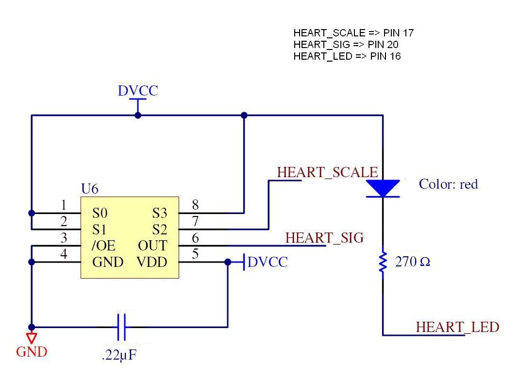
2. Now that you have a properly configured SPI slave, it is time to use the PC-Atmega USB connection to transmit some useful information. MAKE SURE YOU REMOVE POWER BEFORE ATTACHING OR REMOVING WIRES. First, remove the accelerometer and associated wires from your breadboard. Attach the heartrate monitor to your breadboard and wire it up according to this schematic. The HEART_LED in the schematic should point into your finger when you put your finger over the light sensor. This sensor uses light levels to determine your pulse. When your finger fills with blood, the light level drops.
3. Power on your bread board. Use the oscilloscope to verify that you have your heartrate monitor connected properly. Note that the period changes as the light level changes. Try placing your finger over the light sensor to see if you can see a change in the period on the oscilloscope (Note: Some people will easily see a large 'jump' while others will barely be noticable. You can try slightly increasing your heartrate if you don't see a change. It's important to not move your hand when you try to measure your pulse, so try to rest your arm and hand on the table and rest your finger on the sensor.) Also, the light sensors are extremely sensitive to the lights above the lab stations. It is recommended you turn those off before taking any measurements. You can observe what happens when those lights are on with your oscope.
4. Download the USB-SPI starter code for the PC application located here. This code is a slightly modified version of the SPI-USB sample code you used earlier. In this lab you will be sending multiple bytes in multiple directions so you will need to develop and implement a protocol. Your protocol will need to operate under a polling model initiated by the PC master.
5. Implement
a program on the Atmel that uses timer 1 input capture mode to determine the
period reported by the heartrate monitor. To do this, time the length of the
period (rising edge to next rising edge). Note: Rather than reporting the
period each time it is recorded, you may want to consider reporting a value
averaged over several measurements.
NOTES:
* You should choose as small a pre-scalar factor as possible for Timer 1 to
increase the accuracy.
* Use TCNT1 and ICR1 to access 16-bit values instead of using the 8-bit
registers (i.e. ICRL & ICRH and TCNT1L & TCNT1H)
* Remember to set TCNT1=0 when you want the counter to restart at 0. The input
capture interrupt does not reset TCNT1 to zero automatically.
Fill in your own
code in processByte() in the USB-SPI PC application to print out the period
data received from the Atmel. Place your finger over the heartrate monitor and
record 10-15 seconds of data on your computer. Plot this data using excel in
order to see the heartbeat pulses. Note: The easiest way to do this is to just
print a list of numbers, copy them from the command shell, and paste them into
an excel spreadsheet.
6. Further modify the code in processByte() to detect the heartbeat pulses and calculate the current heartrate. Once you've done that, you should continually send the currently detected heartrate back to the Atmel processor.
7. Modify your microcontroller code so that one of the tri-color LEDs blinks at the user's heartrate. Take your pulse with a stopwatch and find your average heartrate. The blue LED should blink when the rate is <-5 beats slower than your average. The green LED should blink when the rate is +/-5 from your average. The red LED should blink when the rate is >+5 from your average.
Question 3: Describe your protocol for
sending bytes back and forth on the SPI interface.
E-mail a single .zip file containing all required documents to cse466-tas@cs.washington.edu
For all files turned in, the comments at the top of the file should contain: