CSE 466 Lab 5: Introduction to the iMote2 and Embedded Linux
Introduction
Now that you've worked with a simple 8-bit microcontroller, we'll be exploring more powerful embedded devices. For the rest of the quarter, we'll be using the iMote2, which has a 32-bit, 415 MHz ARMv5 microcontroller (The PXA271), with 32 MB of Flash, and 32 MB of RAM. This microcontroller was designed for use in cell phones and PDAs. This lab will introduce you to the iMote2 platform, and using Linux as an embedded operating system.
WARNINGS!!!
- NEVER attach or detach the imote from the debug board or the sensor board when power is attached. ALWAYS make sure you've unplugged ALL of the USB cables when connecting or disconnecting the sensor board or debug board.
Objectives
In this lab, you will learn:
- How to write user-level applications and load them onto the iMote2
- How to write, load, debug, and use Linux kernel modules
- How to use the PXA271's hardware timers
- How to control sensors and peripherals on the iMote2
- How applications communicate with devices in Linux
- The basics of the Linux character device model
Suggested Reading and Resources
Part 1: Getting acquainted with the platform
In your kit, you will have three boards:
 |
 |
 |
| The iMote2 |
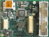
The Debug Board |
The Basic Sensor Board |
The debug board features the same USB interface chip you used in lab 4. It lets you tap into the iMote2's serial ports, SPI bus, and I2C bus. In addition, it contains a JTAG interface for programming and debugging the iMote2. We'll be using this board to access the iMote2's console. The Basic Sensor Board contains an accelerometer, light sensor, temperature and humidity sensor, and a general-purpose ADC converter. In this lab, we'll be using the accelerometer.
We've pre-loaded the Linux kernel, the filesystem, and the bootloader (BLOB) on your iMote2 using the JTAG interface. You should be able to follow these directions and log into the iMote2:
- Attach your iMote2 to the debug board, and connect the debug board to your computer with a USB cable.
- Double-click the uCon iMote2 icon on the desktop.
- Press the power button on the iMote2. The tri-color LED should turn white for a second, and then turn blue. You should see the boot sequence in your window.
- Once you receive the login prompt, log in with the username root and the password rootme.
UPDATE:
The iMote2s aren't necessarily appearing on COM2. Sometimes they're COM8, sometimes they're COM13. Look at your Device Manager (MyComputer->Properties->Hardware->Device Manager) under "Ports (COM & LPT)". It'll be the higher of the listed USB serial ports. You can use any terminal program (HyperTerm, etc..) to connect to the mote. Settings for terminal program: 115200/8/none/1/none. For some programs you may have to boot the mote first (disconnect power, reconnect power, hit button, right when the LED turns blue) before connecting with a terminal program.
Now that you've logged in to your iMote2, let's compile our first kernel module and user-level application!
- Download and unzip the Blink application code to your attu account.
- To compile the kernel module, simply run
make. This should produce a file called blink.ko, which is the kernel module.
- To compile the application, run:
/cse/courses/cse466/iMote2/cross-compiler/arm/3.4.1/bin/arm-linux-gcc -o blink-app blink-app.c
This should produce a file called blink-app, which is a user-level utility to set the blink rate.
- Copy the files over to the iMote2 using WinSCP3. To do so:
- Plug in your iMote2 directly to your computer with a second USB cable. This establishes a network connection between your computer and the iMote2. The iMote2 emulates a USB Ethernet device. UPDATE: The usb ethernet should automatically come up, but if not, go to your terminal program that is logged into your iMote2 through the debug board. Type "ifup usb0". You can check to see if it worked by opening a command window on your Windows machine (Start->run->"cmd") and typing "ipconfig" You should see an interface with an address of 192.168.99.100.
- Launch WinSCP3 from the desktop.
- Click �New.�
- Enter 192.168.99.101 (the iMote2's IP address) as the hostname, root as the username, and rootme as the password.
- Optionally click �Save� and �OK� to save the settings for use next time.
- Click "OK."
- Drag the files from your O: drive (o:\unix\homes\iws\<username> maps to your Unix home directory) to the WinSCP window.
- To load your kernel module, run
insmod blink.ko on the iMote2 console. For more information on insmod, see the manual page.
- In Linux, like all other Unix-like operating systems, devices appear as special files. Devices can either be character devices, which act like infinite streams of bytes, and block devices, which communicate with fixed-size blocks of data. Devices are part of the regular filesystem namespace, usually appearing under the
/dev directory. For each device "file," the filesystem contains an entry mapping that "file" to a device number, split into major and minor parts. Major numbers correspond to a particular kind of device, or a driver responsible for that device. Minor numbers correspond to specific instances of those devices, which are managed by a common driver. You can view these major and minor number by running ls -l /dev.Since the number of major device numbers is small, well-behaved drivers request a major number when they are inserted into the kernel. Now that the kernel module has been loaded, we need to find out which major device number Linux has assigned to our new device. To do so, run cat /proc/devices. Under "Character devices," you should see a line like 254 blink. In this case, 254 is the major device number. Since we only have one blink device, we use 0 as the minor number. To make a filesystem entry for the blink device, run mknod /dev/blink c 254 0. This creates a character device named /dev/blink that points to device number 254,0. For more information on mknod, see the manual page.
- Execute
./blink-app 1 to blink the LED at 1 Hz.
- To remove the blink module, execute
rmmod blink. For more information on rmmod, see the manual page.
Part 2: Extending the blink module
Now that you've successfully built a kernel module and an application that uses it, let's take a look at how it works. From there, you'll extend the blink module to drive three PWM signals to the tri-color LED (similar to lab 3).
Let's take a look at the blink-mod.c file.
- At the top, you'll notice several headers are included. The quick reference guides at the back of chapters 2-4 of Linux Device Drivers will tell you which header files you need for various kernel functions and data structures.
- The
MODULE_AUTHOR, MODULE_DESCRIPTION, MODULE_VERSION, and MODULE_LICENSE macros embed information into the final kernel module file.
- The blink_fops structure points to supported file operations that can be performed on the device. A pointer to this structure is passed when registering the driver. For more information, see chapter 3 of Linux Device Drivers.
- The module_param macro lets you declare parameters that can be specified when the module is loaded. For more information, see chapter 2 of Linux Device Drivers.
- The
blink_ioctl function receives all ioctl() calls on the device file from user applications. ioctl() is used for sending commands and setting and querying configuration information to and from the device when regular "read" and "Write" semantics don't fit. For example, ioctl is used to eject CD-ROMs, set serial port baud rates, etc. For more information about ioctl, see chapter 6 of Linux Device Drivers.
- The
blink_irq_handler function is called when the timer interrupt is fired. Note that on the PXA271, the interrupt for timers 4 through 11 are shared, and you must inspect the OSSR register to see which timer has fired. See the PXA271 Developer's Manual for more details. If the interrupt is not handled, IRQ_RETVAL(IRQ_NONE) is returned. If the interrupt is for this module, IRQ_RETVAL(IRQ_HANDLED) is returned. Chapter 10 of Linux Device Drivers has more information on interrupt handling under Linux.
init_function is the function called when the module is loaded. Its responsibilities include allocating a major device number, allocating a character device for that device number, pointing the character device to the structure of available file operations, registering the interrupt handler with the kernel, and setting up the hardware timer. Note that unlike main, the function name isn't anything special -- a macro at the bottom of the file declares which function performs initialization.unload_function is called when the module is unloaded. It unregisters the interrupt handler and frees the character device and device number. Note that if a module doesn't clean up properly, the kernel will likely crash (called a "kernel panic") since data structures inside the kernel will point to code and datathat's no longer there. Like init_function, a macro at the bottom of the file declares which function should be called when the module is unloaded.
Now, your task is to modify the blink module and application so that you can set the tri-color LED to any color using PWM. Specifically:
- Modify the blink kernel module to generate PWM signals to all three LEDs, like you did in lab 3. You should be able independently control each LED�s duty cycle.
- Modify blink-app into a user-level application that sets the color output of the tri-color LED. You�ll need to extend the kernel module�s ioctl interface for this.
Part 3: Using the accelerometer
In this part, you'll finish implementing a driver for the accelerometer on the Basic Sensor Board, and write an application that converts accelerometer readings to colors, like in lab 3.
- Download the accelerometer skeleton code here. It should contain the following files:
- st-accel.h -- header file for accelerometer driver, shared between the module and application
- accel.c -- accelerometer driver skeleton code
- accel-dump.c -- program that continually reads and displays accelerometer values
- Before getting started, here's some things to note about the skeleton driver:
- In addition to the
ioctl syscall, the read syscall is implemented. The driver emits a stream of sensor readings that can be read with read. If no sensor readings are available, the application sleeps until data is available.
- To read from an accelerometer register, use the
accel_read_reg function. To write to an accelerometer register, use the accel_write_reg function.
- A GPIO interrupt is triggered when data is ready.
- The
ssp_* functions are part of the Linux kernel, and interface with the PXA271's synchronous serial port controller. See /cse/courses/cse466/iMote2/sources/linux-2.6.14/include/asm/arch-pxa/ssp.h for more details.
- You can write data into the circular buffer read by the application by calling
write_data_into_buffer.
- Since the driver simply produces a stream of bytes, the accel-dump application expects two sync bytes to proceed each accelerometer reading (0xA5 0xA5).
- Implement
accel_irq_handler and accel_ioctl in accel.c.
- Test your module with the provided
accel-dump application.
- Create an application that translates the accelerometer readings into color values. You do not need to do any fancy HSV to RGB mapping -- simply using each axis of the accelerometer to control a single color is sufficient.
Part 4: Using the radio
In this part, you'll be introduced to the radio funcionality of the iMote2. We give you all of the radio sending and receiving code, but you have to define your own packet structure.
- Download the radio code located here. It should contain the following files:
- tosmac.h -- header file for the radio driver
- CntToLedAndRfm.c -- program that continually increments a counter, displays the value on the LEDs, and broadcasts that number using the radio.
- RfmToCntAndLed.c -- program that continually listens for incoming transmissions, reads the count from the packet, and displays the current count on the LEDs
UPDATE: You will also need the triled LED driver located here. Remember, you will have to create the device /dev/triled.
UPDATE 2: Turns out there's a conflict between your PWM driver and the radio driver both attempting to use IRQ7. In order to remedy this download the new radio driver located here and put it in the folder /lib/modules/2.6.14_r1.0/kernel/drivers/tosmac . In your PWM driver you also need to update the call to "request_irq()" the argument which is currently "0" should be changed to "SA_SHIRQ".
- Using both of your iMote2s, load CntToLedAndRfm onto one of the nodes, and load RfmToCntAndRfm onto the other
- Note: The code in CntToLedAndRfm is just broadcasting packets. If other groups around you are running CntToledAndRfm your node may be receiving their packets as well as your own.
- Implement a packet structure and modify both applications so that your receiving node will only respond to your sending node. How you structure your packet is up to you, but you must at least use a unique identifier and a node ID.
- Use your lab group number as your unique identifier.
- Your choice of node id is arbitrary
Part 5: Putting it all together
In this part, you'll combin the elements from Parts 1-4 and add bidirectional communication between your iMote2s.
- Using the moduels you've developed above create two programs for you iMote2.
- The first program should read your accelerometer value and send that reading out over the radio using the packet structure you defined above.
- The second program should receive those readings over the radio and output the assocated values on the PWM controlled LEDs
- UPDATE: You will use the accelerometer here, not the light sensor. Additionally, your receiving program should monitor its own accelerometer and send a binary result to the sending node. I.E. If the accelerometer is flat, the node should send an ON. If the accelerometer is tilted past some angle (you choose) the node should send an OFF. You only need to implement this for 1 direction (i.e. just turning the node left is fine). You should send the ON/OFF packets at some periodic rate of your choice.
- Your sending node should respond to this packet by ceasing to send packets and updating it's own LEDs instead. Once the sending node receives an ON packet, it should resume sending packets and stop updating it's own LEDs.
Deliverables
E-mail a single .zip file containing all requird documents to cse466-tas@cs.washington.edu
For all files turned in, the comments at the top of the file should contain:
- Both partners' full name, login and student number.
- The lab number and the part of the lab (e.g. "Lab4, Part2").
- Demonstrate your system of sensor to radio to radio to LEDs to a T.A. You can either do this during lab, or during the first 1/2 hour of the next lab.
- Grading will focus on if it works, and reasonable responsiveness
- Turn in a soft copy of your commented C code. You only need to turn in your application for part 5, and any driver code that you modified for any of the parts of the lab.