Overview
The DesignKits contain everything that you need to construct
and test medium size circuits. They include:
- A solderless breadboard (protoboard)
- Power supply
- Logic probe
- Clock generator (pulser)
- Box of pre-cut wires
- Wire stripper/cutter
- Some standard TTL chips and PLDs
- Switches, LEDs, resistors
You will be provided with other devices throughout the
quarter and will add these to the list provided in your
Design Kit. Accidents do happen, so we will replace a
certain number of damaged chips (if there is a reasonable
explanation for the damage). However, you will be held
responsible for the cost of the chips if there is repeated
and/or careless damage.
Your DesignKit contains a pair of long nose pliers. Please be very
careful with these to avoid damaging the tip. You will find these
invaluable for inserting and removing wires in crowded protoboards.
They are also useful for straightening hook-up wire and bent pins on
the chips. You may want to buy a small screwdriver. The screwdriver
is an acceptable tool for carefully removing chips from the
protoboard. (There is also a less effective chip puller in the
DesignKit.)
Breadboarding Techniques
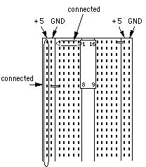
The protoboard in the DesignKit is comprised of several
sections as shown in the figure on the next page. Power and
ground have been pre-wired into the boards from the power
supply connector and assigned to the vertical busses marked
in Black/Green (GND) and Red (+5v.) Terminals in the
protoboard are connected internally as shown in the figure.
The kit includes some wire that has been pre-stripped and
bent so that it can be easily inserted in the protoboard.
If you need wire of a different length, use the wire
stripper to cut and strip the wire. But first adjust the
stripper so that it cuts the insulation without nicking the
wire itself. The protoboard terminals are designed for wire
of size #22-26. Inserting anything larger than size #22
wire will damage the terminal. Always straighten out bent
wires and pins before inserting them into the board. You
will also notice that new IC chips have pins splayed out for
use in automatic insertion machines. You will have to
carefully bend them together a bit before inserting the
chips into the board (use pliers or the table top).
Before doing any work on the protoboard such as wiring and
inserting/removing chips, be sure the power is OFF. That
it, unplug the power connector while you are constructing
the circuit. After you have finished wiring up your design
and before you turn on the power, double-check the power and
ground connections. To be sure, you should measure the
resistance between power and ground to check for a short
circuit.
Wiring Guidelines
- Arrange the IC chips on the protoboard so that only short wire
connections are needed.
- Try to avoid a jungle of wires (guaranteed to save you lots of
time and trouble later).
- Try to maintain a low wiring profile so that you can reach the
pins of the chips and so the chips can be replaced if necessary. The
best connections are those that lie flat on the board and do not cross
over any chips.
Using the Logic Probe
The logic probe provides a very convenient way to check the
value of any signal in your circuit. The probe has two
lights, HI and LO, which indicate the value of the signal.
The logic probe responds to the input voltage in two ways
depending on whether CMOS or TTL is selected. We will use
the TTL setting which lights the LO light for voltages
<0.8v. and lights the HI light for voltages >2.4v. If
neither light is lit, then the signal is floating (i.e., not
being driven) or has an illegal value somewhere between 0.8v
and 2.4v.
The logic probe is also used to "catch pulses". If the
PULSE MEMORY switch is placed in the MEM position, the PULSE
indicator will turn on as soon as a transition, high or low,
occurs on the input. This convenient for determining if a
signal changes when the change happens too fast to be
visible. This is useful for detecting glitches and whether
a wire is stuck at a fixed value or is, in fact, changing on
occasion.
Using the Switch Paks
You will be using switches to generate inputs for the
circuits you test and LEDs to display the outputs. You may
want to reserve part of your protoboard for a set of
switches and lights which you can use for the rest of the
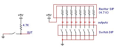
quarter. The simplest switch is the the single-pole, single-
throw switch shown in the figure below. To use the switch
to generate a 1 or 0, we must connect it as shown. Note
that this configuration generates a 0 when the switch is
connected.
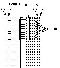
We will be using switches that come in packs of 8 and
resistors that come in packs of 8. These can be easily
connected as shown in the following picture to give 8
separate switches. First measure the resistance of the
resistors in the resistor PAK to figure out which is pin 1
(common) and then connect the switches as shown. Choose an
place like the first strip where you can leave these
switches for the entire quarter.
.
.
.
Light-Emitting Diodes (LED)
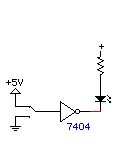
LEDs convert electrical current to light. They can be used
as simple optical output devices. The circuit below shows
one of many ways that a TTL gate can drive an LED. The
resistor is used to limit the current flowing through the
LED. An unprotected LED connected between ground and +5V
will burn out. The resistor also protects the output
circuitry of the TTL gate.
The LED is a diode, and thus its two connections are
electrically different. How can you tell them apart? Here
are some hints; they do not always work, though. The longer
lead of the LED is the cathode, i.e., the wire that goes to
the lower voltage. If the plastic housing is not circular,
the flat part corresponds to the cathode (the flat part in
the symbol). You can prepare a simple "LED test station" on
your superstrip, using a 330 ohm resistor connected to +5V and
a grounded pin next to it. In this set-up, you can easily
test any LED both ways and determine which lead is the
cathode.
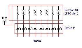
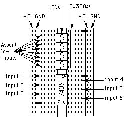
We also have LED's in paks of 8 or 12. The next figure
shows how they look internally and how to connect them up
conveniently on your protoboard. First measure the
resistance of the resistors in the resistor PAK, then
construct the LED circuit shown in figure using the LED Pak.
Choose an place like the first strip where you can leave
these switches for the entire quarter. You will want to
install a 74LS05 or 74LS04 inverter chip (or perhaps a
74LS240 buffer chip) in order to have active high inputs to
the LEDs. (For clarity, the connections between the
inverter outputs and the LEDs are not shown in the figure.)
.
.
.
Clock Generator
Each kit contains a clock generator. Its red and black clips
should be connected to power and ground. The tip is the clock
output. Since the output is open collector (meaning the output will
be pulled down for a `0', but left floating for a `1') you need to
connect a 1K Ohm pull up resistor to the output. Connections to the
output of the clock generator
are made by placing the small rubber tube on the tip. This tube serves
as a sleeve and a wire can be inserted in the sleeve.