Lab components
(Spring 2000)
Introduction to Microcontrollers
Objectives:
This lab will require you to:
- Learn about your XS40 board
- How does the microcontroller interface with other components?
- Learn about the Keil Environment
- Load a project in Keil
- Compile (build) a Keil project and run it on the microcontroller
- Learn how Keil C interfaces with the microcontroller
- Upgrade your board for the new microcontroller
- Wire a switch to reset the microcontroller
- Wire an LED to verify the reset state
- Program the flash memory using the Data I/O machine
- Run the previous programs on the new microcontroller
Reading
This lab has two
handouts:
- XS40 board pin-out
- Keil docs -- Chapter 3
Part1--Learning
the Keil environment
1. Get XS40 board, plug in parallel cable, plug in the XS40 power supply.
2. Double Click the icon "GXSTEST" on your Desktop. Select "board type"
to be XS40-010XL and the correct port (usually LPT1) and test it.
3. Double Click the icon "GXSSETCLICK" on your Desktop. Select "board
type" to be XS40-010XL, the correct port (usually LPT1) and the "Divisor"
to be 8. This will set the clock frequency to be 100Mhz/8 ~ 12.5 Mhz.
4. Goto \\ifilesvr1\courses\cse477\Spring2000\lab1\
5. Copy all files to your local network drive (z:\< your_login > \ mylab1). I'll refer
to this directory as "mylab1".
6. Run (from start menu) programs/Keil PK51/uVision-51.
7. Select Project/New Project... from the Keil menu.
8. Select your Z: drive and your "mylab1" directory, and name the project
"ledreg.prj".
9. Click the "Add" button and add "ledreg.c".
10. Save the project.
11. Goto File/Open and open ledreg.c.
11. Build the project. Either goto Project/Make: Build Project or push
the shortcut button (three down arrows pointing at a rectangle).
It should say "Make successful. HEX file created."
Part
2--Programming the board
1. Open up a command prompt window. Goto to your z:mylab1 directory.
2. Type "xsload ledreg.hex ledreg.bit". This will load the hex
file into the memory and the bit file into the FPGA.
3. Type "xsport 1" followed by "xsport 0". The FPGA is wired
to reset the microcontroller through the parallel interface. These
two commands toggle the low order bit of the 8-bit parallel port, effectively
resetting the microcontroller. Your ledreg program should now be
running.
4. Modify ledreg.c to light up the outer LED segments (i.e. the segments
used in a 0) one at a time in a clockwise pattern.
Part
3--Upgrading the Microcontroller
1. Unplug the 9V supply and the parallel cable.
2. Remove the microcontroller carefully with the chip
puller clips. Make a note of the orientation of the microcontroller.
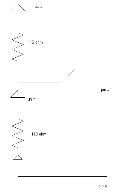
3. Get a switch and an LED light.
4. Install the switch and LED according to the diagram below.
5. To program the new microcontroller, you will use the DataI/O 2900
programmer. First copy the hex file from your compiled program to
a floppy.
6. Take the floppy to the 2900 and follow the programming
instructions .
7. After the microcontroller has been programmed, insert it carefully
back into the socket, making sure that the dot on the microcontroller points
towards the FPGA.
8. Switch the jumper (EXT) to turn off external memory.
9. Get one of us to check your setup before powering back up.
10. After you power up, push your reset switch until the LED light
goes off.
11. Now download the Xilinx program. See if your program (the
hex file generated above from the compiled program) works.
Part
4--Using the SFR P1 port for the LED
1. Get ledport.c, ledport.bit from u:cse477/lab1
2. Look at ledport.c. The new bit file wires the FPGA to connect
the LED to the P1 port of the microcontroller.
3. Build, compile, download, and run the program
4. This FPGA bit file maps the MSB of P1 (bit 7, i.e. P1.7) to
the second bit of the parallel port. Change the program to do something
interesting (like changing direction of rotation, or speed of rotation
depending on the whether bit is 0 or 1) with the LED when this bit is toggled.
Use the "sbit varname = P1^7;" declaration to reference this bit's value.
What
to Turnin
Turn in your C program that rotates the 7-segment display LEDs and
the new program you made for the P1.7 bit.
Demonstrate your implementation that uses this program and have us
sign off on the C programs.
Last Updated:
3/24/2000