Panoramic Stitching
By: Gaurav Bhaya and Atri Rudra

1. Introduction
Panoramic Stitching is a method of creating a panoramic
(a full 360 degrees) view from consecutively clicked pictures from
a camera. Creating a panorama primarily involves the following stages.
- Taking Pictures: The most common method of taking
pictures is by using a camera with a tripod and a Kaidon head. Consecutive images
may be clicked by rotating the camera by a certain angle allowing
some overlap between consecutive images. Using a tripod (as opposed to
clicking in hand-held mode) is
important because the camera must be rotated about its focus for
best results.
- Warping Images: Images taken from a camera are deformed
by the camera lens. As a result of which the individual pixels of the
image may be displaced with respect to their true position. Therefore,
the images need to be warped before they are stitched together to
reduce the error in the region of overlap.
- Stitching Images: Images need to be stitched such
that there is a smooth transition from its individual images.
Therefore, it is required that the amount of overlap between the
two images is determined. We use the Lucas-Kanade iterations to
calculate the displacement between successive images and place
the individual images in correct order .
- Blending Images: In the region where two images overlap
we use a simple 1-D feathering (the blending is by the hat function)
to smoothen the transition.
- Cropping Final Image: To complete the panorama one has
to clip half of the (left side of) the first image and (right side)
of the last image (the first and the last images are the same but are
placed as "different" images in the last three steps to complete
the 360 degree view.
2. Warping Images
Relative distance between two points in space is not maintained in a image
produced by camera. Hence, comparison of two images directly captured by a camera
is likely to lead to errors. Therefore, the images need to be warped around
a cylinder (field of view for the camera) and re-projected on the plane from the point of
view (focus) onto a plane such that the relative distance between two points
is maintained irrespective of the angle of viewing.
For this purpose we require the focal length of the camera lens. Further,
lens (camera lens) is prone to errors for refracted rays away from the center of the
lens. Therefore, we need to apply a correction using constants k1
and k2 for a lens.
In summary, the steps involved are as follow:
- Warp the image on to cylinder,
(sin a, h, cos a) = (x', y', z').
- From the center of the cylinder project every point onto plane with z=1 (or
in other words normalize the coordinates to z=1).
3. Lucas Kanade Algorithm
Neighboring images must be placed such that the error in the region
of overlap is minimized. Trying this out for every x and y value
for overlap is definitely not a good solution.
The Lucas Kanade algorithm is an iterative algorithm which successively
improves the quality of overlap between the two images. The
algorithm is as follows:
Let A represent the matrix that corresponds to the image gradient for every
pixel along the x and the y directions as it's two columns. Further let b be
the vector of the difference in intensities between the two images. One can derive
that the displacement t between the two images is the vector which
minimizes the norm of At-b. This is equivalent to solving for the system of
equations given by ATAt=ATb. Note that this is
a system of two equations in two unknowns.
This procedure however, may get stuck at a local minima and one trick to avoid getting
stuck in a local minima is to make a hierarchy of the image at different levels of
detail. The first cut of t is got by Running an iteration of Lucas Kanade on
the coarsest version of the two images and then refine the value by going down the
hierarchy to the finest.
4. Blending Images
The last step gives us the overlap between two consecutive images. However, to make
the transition smooth one has to blend the two images. We use a simple
1-D feathering technique. We specify a blending window w, that is for the
first w pixel wide band in the overlap region, for each pixel (x,y) set
the final intensity of the blended image as I(x,y)=(1/w)[
x*IL(x,y)+(w-x)*IR(x,y)].
5. Successes and Failures
We experimented some techniques to minimize the human intervention required to
build a panorama.
- One of the important component required for creating a panorama is the value of
the focal length for the lens. Though focal length for the camera can be determined
to some extent using various trick but this usually involves taking a whole set of
different images, which could be tedious. We attempted to study the value of the
function minimized by Lucas Kanade technique which unfortunately did not
reach a local/global minima near the focal length.
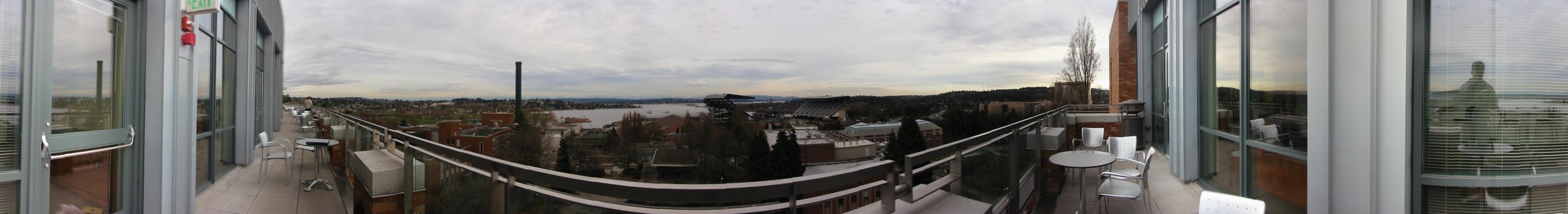
- The following two images were obtained during the process of creating a panorama.
Because of the pseudo one dimensional nature of these images Lucas Kanade
technique failed to align the images correctly in the y direction. In fact the
error was even larger when the images were clicked without placing the camera on the
tripod.


- Lucas Kanade technique requires a good initial value for the displacement. We used
simple column by column comparison of the images to generate a set of local minimas which
are good candidates for initial displacement to Lucas Kanade algorithm. The following is an
image created without using a tripod stand.

- Images created in the hand-held mode did not blend smoothly. It lead
to creation of distinct marks at the location of blend (in the right half of the above
image). Observations revealed that this
was owing to the fact that the images were displaced from each other in an angular
manner which lead to imperfect blend.
- Often a 360 view is not required. We added an option whereby, one can add an
extra image (patch image) to patch the first and the last image together
to that it can still be view in the form of a circular image.
- Aligning the images: Due to successive errors in Lucas Kanade
there can be vertical drift between the first and the last image. We use
linear warp to the mosaic to remove any such drift. This wrap of the
form y' = y + ax, transforms the y coordinates of the mosaic such that the
first image has the same y-coordinate on both the left and the
right end.
- Blend width calculation: For every two consecutive images
we calculate the width of the overlap and the return the minimum among
all such values as the blend width or w.
6. References
Lecture notes and slides at CSE 455 webpage.