Subdivision Surfaces
Final project for CSE 557, Winter 2007
Laura Effinger-Dean
For my final project, I implemented the Loop and modified Butterfly subdivion schemes,
Starter code
I started with skeleton code from the Spring 1999 offering of CSE 557.
The code uses MFC for GUI components and includes a framework for edges
and vertices. It also included code for doing simple midpoint
subdivision and a starter point for generating normals.
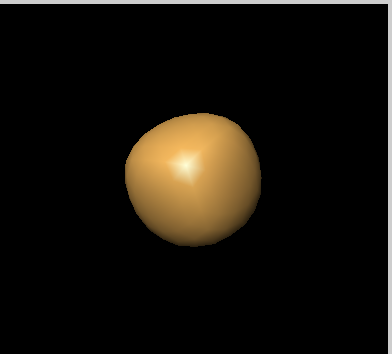
Loop subdivision
The Loop subdivision scheme is an
approximating scheme. At each subdivision step, we apply an average
mask to all vertices. This differs from interpolating schemes, in which
only newly created points are averaged. I used the averaging mask from
[1]. Here are some results:
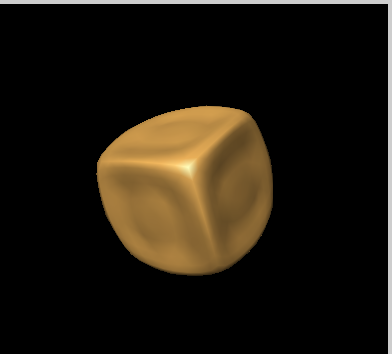
A cube at subdivision depth 0, 1, 2, 3:


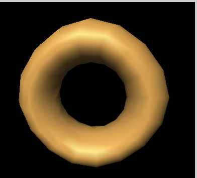
A donut at subdivision depth 0, 1, 2, 3:


Modified Butterfly subdivision
The Butterly subdivision
scheme is an interpolating scheme. Only new points are averaged, and
all averaged locations are on the limit surface. The modified
subdivision scheme improved upon the original Butterfly scheme by
reducing degeneracy at "extraordinary" vertices - i.e., vertices with a
valance other than 6. I used the weights given in these slides.
A cube at subdivision depth 0, 1, 2, 3:


A donut at subdivision depth 0, 1, 2, 3:


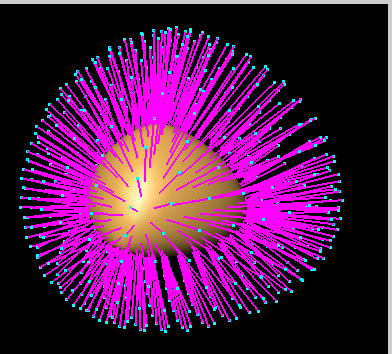
Tangent masks
I also compute the normals to the surface at each level for each
scheme. For the Loop scheme, I used the weights given in [1]; for
Butterfly, I used the weights given in [2]. In these images we can see
the normals that are generated for Loop and Butterfly, respectively:

Evaluation mask
A further step we take after subdividing
and averaging is to apply an "evaluation mask" to push the vertices to
their locations on the limit surface. For the Butterfly scheme, this
step is unecessary because the averaging mask already pushes points to
the limit surface. For the Loop scheme, I used weights from [1]. Here
are some images drawn with and without the evaluation mask:


Feature edges
I also implemented an extension to Loop
subdivision which allows certain edges to be tagged as "feature" or
"crease" edges. The vertices on these edges use a different averaging
mask which only uses the positions of other vertices on the same crease
to calculate a new position, leading to a "sharp" edge. It is possible
to select crease edges in the editor by selecting feature vertices; any
edge between two feature vertices is a feature edge. I used the mask in
[2] to calculate the averaged position of crease vertices.
A tetrahedron with and without a feature edge:


A cube with and without a feature edge:


Bibliography
[1] Stollnitz, DeRose, and Salesin. Wavelets for Computer Graphics . Morgan Kaufmann, 1996.
[2] SIGGRAPH 2000 Course Notes: Subdivision for Modeling and Animation. http://www.mrl.nyu.edu/publications/subdiv-course2000/coursenotes00.pdf
[3] Zorin, Schroder, and Sweldens. "Interpolating Subdivisions for Meshes with arbitrary topology." SIGGRAPH '96.