Computer Vision (CSE 455), Winter 2012
Project 3: Single View Modeling
Assigned: Wednesday, Feb 8, 2012Project Due: Tuesday, Feb 21, 2012 (by 11:59pm).
Artifact Due: Thursday, Feb 23, 2012 (by 11:59pm)
Head TA: Supasorn Suwajanakorn (ask him first!)
TA: James Gray
As part of this project, you will be producing digital artifacts. The class will vote on the best artifacts.
You need to have a file named voting.jpg in your turnin/artifacts folder (not in a subfolder). This will be considered as your submission for the voting. It should be a full-resolution copy - we will produce thumbnails as needed.
Intro
In this assignment, you will fill in various routines and ultimately create 3D texture-mapped models from a single image using the single view modeling method discussed in class. The steps of the project are:
- Image acquisition
- Calculate vanishing points
- Choose reference points
- Compute 3D coordinates of several points in the scene
- Define polygons based on these points.
- Compute texture maps for the polygons and output them to files.
- Create a 3D texture-mapped VRML model
- Create a reverse perspective paper cutout of the object.
- Submit results
Get Started
Before you continue reading, we recommend you first familiarize yourself with the user interface in solution executable. Then, try to do step 1-6, which we describe in more details below, using our solution executable to get a sense of what the program can do and how to create a 3D model.
Once you're comfortable with the UI and tool, you can then follow "todos" in blue boxes in each of the steps. Also, here's a summary Todo page that re-lists all todos. Before you start coding, you should try to understand basic data structures used in the program and check out utility classes such as vec3d, Mat4d (mentioned on the same page). Also, if you get stuck, here's a list of useful hints for working on this project, and don't forget our discussion board which usually contains useful information and common confusions.
Image Acquisition
For this assignment you should take high resolution (preferably at least 800x800) images or scans of at least two different scenes. One of your images should be a sketch or painting. For instance, a photo of a Greek temple and a painting of Leonardo da Vinci's "The Last Supper" might be interesting choices. (We don't want everyone in the class to do these objects, however.) Note also that the object you digitize need not be monumental, or be a building exterior. An office interior or desk is also a possibility. At the other extreme, aerial photographs of a section of a city could also be good source material (you might have more occlusion in this case, necessitating some manual fabrication of textures for occluded surfaces). Be sure to choose images that accurately model perspective projection without radial distortions. You'll want to choose images that are complex enough to create an interesting model with at least ten textured polygons, yet not so complex that the resulting model is hard to digitize or approximate.
Calculating Vanishing Points
Choose a scene coordinate frame by defining lines in the scene that are parallel to the X, Y, and Z axis. For each axis, draw more than two lines parallel to that axis and try to make them as long as possible and far apart in the image. The intersection of these lines in the image defines the corresponding vanishing point which may be "at infinity". Use high resolution images, and use the zoom feature to specify line endpoints with sub-pixel accuracy. A small number of "good" lines is generally better than many inaccurate lines. Use the "save" feature in your program so that you don't have to recalculate vanishing points every time you load the same image.
TODO: BestFitIntersect() in svmmath.cpp
Compute the best intersection point of 3 or more lines in a least squares sense. Here is a write-up for a recommended method that extends the cross-product method discussed in class to return the best intersection point of 3 or more lines in a least squared sense.
Choose Reference Points
You will need to set the reference points as described in lecture. One way of doing this is to measure, in 3-D, when you shoot the picture, the positions of 4 points on the reference (ground) plane and one point off of that plane. The 4 reference plane points and their image projections define a 3x3 homography matrix H that maps X-Y positions of points on the ground plane to u-v image coordinates. The fifth point determines the reference height R off of the plane, as described in lecture. Alternatively, you can specify H and R without physical measurement by identifying a regular structure such as a cube and choosing its dimensions to be unit lengths. This latter approach is necessary for paintings and other scenes in which physical measurements are not feasible. If you'd like, you can use the X and Y vanishing points as two of the reference points on the plane. In this case, you need to specify only 2 more on the plane and one off the plane.
Once you have specified reference points and push them onto stack, you can run "Tools->Compute Homography" which will compute and store a homography for later use.
TODO: ComputeHomography() in svmmath.cpp
Compute the homography H from the plane specified by points to the image plane, as well as Hinv, the inverse of H. This is used to compute the homography for the reference plane, as well as the polygonal patches you create. In case of an arbitrary polygonal patch in 3D space, you need to convert the coordinate system first. See this document for a more detailed explanation.
TODO: ConvertToPlaneCoordinate() in svmmath.cpp
Convert the coordinate of points on the designated plane to the plane coordinate system, as described in above mentioned document. This is called from ComputeHomography to compute homographies from polygonal patches you defined in the scene. Save the final scales you apply to the u and v dimensions to the output parameters uScale and vScale.
Compute 3D Positions
You will compute 3D positions of any new points using your information from the reference points, vanishing points, and homography. To compute the 3D positions, you can combine two different techniques: point: in-plane measurements and out-of-plane measurements which are:
TODO: sameXY() in ImgView.inl
Compute the 3D position of a new point that is directly above another point whose 3D position is already known. See the slides for measuring height (Projective Geometry).
TODO: sameZPlane() in ImgView.inl
Compute the 3D position of a new point that is on the same plane as another point whose 3D position is already known. A special case of this is a point on the reference plane. In this case, the reference homography H can be used to compute its 3D position. More generally, see the man on the box slide from lecture (Projective Geometry slide 34), where the given reference point is t1, the new point is m0, and you want to compute the point b0 (once you have b0, you can compute its X and Y positions using H). Note that the man is not used here, we're only interested in a point on the box. You may use vz instead of t0 to help find b0. While you're not given the image position of b1, you can compute it from its 3D coordinates (knowing it has the same X-Y coords as t1 and is on the ground), using H-1.
Besides these two techniques, you will be implementing a set of functions which compute 2D/3D positions of the corners of a box given some existing reference corners:
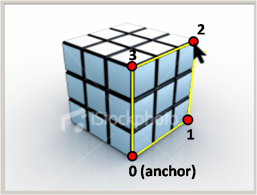
TODO: solveForOppositeCorners() in ImgViewBox.cpp
Given the 2D position of corners 0 and 2 on an XZ rectangle, compute the 2D positions of the other two corners (with indices 1 and 3). You'll need to use the vanishing points and construct various lines to find the points. The indexing of the corners is shown here:
TODO: solveForOppositeFace() in ImgViewBox.cpp
Given the 2D positions of corners 0,1,2, and 3 on a
box, compute the 2D positions of the other four corners (with indices
4, 5, 6, and 7). Again, you'll need to use the vanishing points and
construct various lines to find the points. The indexing of the
corners is shown here:
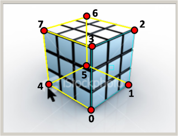
TODO: find3DPositionsBox() in ImgViewBox.cpp
Given the 2D position of all eight corners of a box (indexed according to the previous image), and the 3D position of the anchor (point 0), compute the 3D coordinates of all points. You will want to first implement the sameXY and sameZPlane routines.
Compute Camera Position and Projection Matrix
You can solve for the height of the camera using the horizon as discussed in class (Projective Geometry slide 33). You may find the SameXY routine useful here.
To solve for the X and Y world coordinates of the camera, first imagine a point C0 on the ground plane that lies directly below the camera (this point has the same X and Y coordinates as the camera), as shown in the figure below.
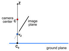
If we can find where C0 projects into the image, sameZplane will tell us its XY coordinates and we'll be done. So where does C0 project? The projection is the intersection of the ray from C0 through the camera center with the image plane. Notice that this ray is vertical---it goes straight up towards the Z point at infinity, [0 0 1 0]T). Notice also that every point on this ray (including [0 0 1 0]T) projects to the same point in the image. Hence, the projection of C0 is the same as the Z vanishing point, vz (pretty neat, huh?). vz in combination with sameZplane gives you the X and Y coordinates of the camera.
You can also solve for the projection matrix П using the homography H of the ground plane. If
![]()
and vz = [uvz vvz wvz]T then П is given by
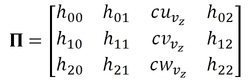
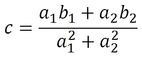
To see why this is true, consider what this projection matrix does to points [X Y 0 1] on the ground plane---it's easy to see that the result is just H [X Y 1]T. It remains to solve for the value of c. To find c, use a reference point P = [X Y Z 1]T that is not on the ground plane, and its known image position (u, v). This point gives us two equations involving c:
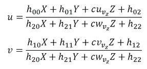
Now multiply both sides of the equations by the denominator of the fraction on the right hand side, and rearrange to get the equations in the form:

The least squares solution for c is then:
TODO: computeCameraParameters() in camera.cpp
Compute the position and projection matrix for the camera, assuming the reference homography and reference height have already been specified.
Compute Texture Maps
Use the points you have measured to define several planar patches (polygons) in the scene. Note that even though your measurements may be in horizontal or vertical directions, you can include planes that are slanted, such as a roof.
The last step is to compute texture map images for each of these polygons. Your program will store a separate texture image for each polygon in the scene, created by applying a homography to the original photo. You need to solve for the appropriate homography for each polygon. If the polygon is a rectangle in the scene, e.g., a wall or door, all that is needed is to warp the quadrilateral image region into a rectangular texture image. More generally, you will need to convert the coordinate system of the polygon to align with the texture image. See this document for a more detailed explanation.
Create a VRML model
For each image you work from, create a VRML model (see documentation below) with at least 10 texture-mapped polygonal faces. The skeleton code will create the VRML file for you but you need to add texture map images and masks for each polygon, in .gif or .jpg format.
Create Reverse Perspective
A reverse perspective is an optical illusion where the 3D geometry is transformed so that depths are inverted--concave scenes become convex and vice versa. However, it is done in such a way that the inverted 3D model appears correct from a certain viewpoint (or range of viewpoints), and it is not until you move your head that you notice that something is wrong. The scene appears to move in the opposite way that it should, and serves to exaggerate the perception of 3D. The artist Patrick Hughes produces stunning examples of this illusion.
While creating reverse perspectives is more of an art than a science, we propose the following approach. First, we must choose the viewpoint from which we want the scene to appear "correct", i.e., identical to the photo from which it was created. One option would be to choose to use the viewpoint from which the photo was actually taken (computed as above). However, this tends not to work well, since the model is typically reproduced at a smaller scale than the original scene, which also scales down the distance from the viewer to the model, requiring the viewer to stand uncomfortably close (the effect works best if you stand a few feet back).
Instead, we assume the viewer far enough away to approximate an orthographic projection, i.e., (X, Y, Z) is projected to (X, Y). We therefore wish to transform the shape of the 3D model so that it appears correct under an orthographic projection. To see how to accomplish this transformation, the perspective projection formula:
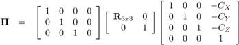
can be re-written as follows:
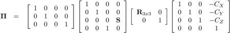
The leftmost matrix above is the orthographic projection matrix. Hence, we can accomplish the reversal by applying the rightmost three matrices to the original shape, as follows:
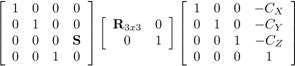
Here, (CX, CY, CZ) is the camera position (we described above how to compute this), and R is the camera rotation. We will provide you with a function that computes R from the projection matrix. We've also added a scale factor S--entry (3,4) in the leftmost matrix--that controls the depth scale of the result. Changing this value stretches the model along the Z direction. This doesn't change the appearance under orthographic projection when looking down the Z axis, but will affect it's appearance when the observer moves. You might want to experiment with different S values to find the one that produces the best illusion. Patrick Hugues constructs his models so that sides meet at 45 degree angles--this may be a good rule of thumb to shoot for and will avoid models that are too shallow or too deep.
Apply this transformation to your 3D model. Then create a physical replica of your reverse perspective by printing out the texture images onto paper, glue-sticking to cardboard, cardstock, or another stiff material, and folding/taping into a 3D recreation of your scene. In general, the larger the physical replica, the more convincing the illusion. Consider using the department's large format printer (the TAs can help you with this if you give them enough advance notice...).
Note that not all scenes will produce good reverse perspectives. Study these examples by Patrick Hughes for examples of scenes that work particularly well. Relatively simple scenes composed of one or more simple box primitives tend to work quite well (use the box tool in the UI).
TODO: invertScene() in camera.cpp
Invert the scene in order to create a reverse perspective image. You'll need to compute a transformation for inverting the scene. The parameter zScale controls how deep the inverted scene will be. Before inverting the scene, you first need to compute the camera parameters.
Submit Results
Put your code and executable in the project 3 turnin directory, and your at least 2 sets of image and its corresponding VRML model in the artifact directory with a web page project3.htm that contains:
- source images, show them both in their original form and with annotations and marks to show which points and lines you digitized (e.g., from a screen shot of the user interface). Give details on where you got the image (name of building, book and page number, artist, etc)
- a still image of a new view of the reconstructed VRML model, fairly far away from the input image.
- some of your texture maps, show some of the more interesting ones, commenting on any hand retouching you did to fill in occluded textures in the background (perhaps show before and after retouching, if it was significant)
- Include at least one non-quadrilateral object to make the scene more interesting.
- VRML files--for each input image.
- Photos of your reverse perspective cutout for only at least one of your scenes.
Bells and Whistles
Here is a list of suggestions for extending the program for extra credit. You are encouraged to come up with your own extensions. We're always interested in seeing new, unanticipated ways to use this program!
![]() Show the camera position in
each VRML file, marked by a sphere or other shape.
Show the camera position in
each VRML file, marked by a sphere or other shape.
![]() Merging models from multiple images. For instance, create a complete model of a
building exterior from a few photographs that capture all four sides..
Merging models from multiple images. For instance, create a complete model of a
building exterior from a few photographs that capture all four sides..
![]()
![]() Extend the method to create a 3D model from a cylindrical panorama.
Hint: parallel lines in a panorama sweep out a curved path--you need to
determine what this curve is.
Extend the method to create a 3D model from a cylindrical panorama.
Hint: parallel lines in a panorama sweep out a curved path--you need to
determine what this curve is.
Resources
- Class lecture notes on projective geometry and single view modeling
- Single view modeling web pages and paper by Antonio Criminisi and colleagues.
- There are also some projective geometry tutorials online.
- VRML: The Virtual Reality Modeling Language, a file format for interactive 3-D models (a.k.a. virtual worlds) on the Internet. We recommend the Cortona browser, which is installed on the machines in the graphics lab. Make sure you install both the Browser and the 1.0 converter. A comparison of many VRML browsers is here. We have put a sample VRML file (it is a text file) online. If your browser has a VRML plugin (you can download these freely over the web), you should see a guy with sunglasses standing on a plank. The guy should look like a cardboard cutout (not a rectangle) if transparency is working. The two texture gif files, floor.gif and io.gif, are in the same directory. More on the VRML file format. Note that we'll only be using a fraction of VRML's capabilities. (Note: for those who can't get the Cortona browser working, try GLView instead, which runs as a stand-alone application)
- Image Editing Tools: We recommend
- Photoshop on Macintosh, PC
- gimp on Unix
Last modified February 08, 2012