Shading Networks Exercise
If you have done the Basic Shading exercise, you should be familiar with creating render nodes and mapping them into specific attributes. This process is basically a "ground level" view of creating a shading network. While useful for simple networks, sometimes it is better to take a higher level view of the shading network. Let's create a simple shader and see what the network looks like.
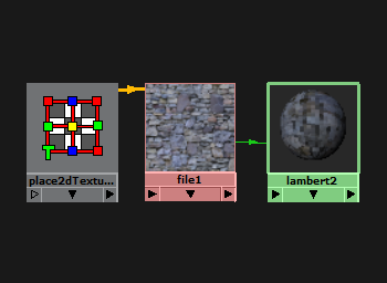
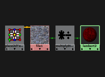
Create a new sphere and assign a Lambert shader to it. Map the this texture into the Color. To view the shading network, open the Hypershade (Window → Rendering Editors → Hypershade). You should see your new shader among the default shaders. Right-click it and select Graph Network from the radial menu. This will display the simple shading network in the Work Area below where the materials are listed. The shading network should consist of a 2D Placement node, a File node, and a Lambert shader.
The orange connector represents multiple connections, allowing us to conclude that the 2D Placement is responsible for many of the attributes of the File. The green connector represents a single connection, in this case the mapping of the File into the Color of the shader. You can view what each connection represents by hovering over the connection with your mouse. For example, the green connection between the File and the Shader should say "file1.outColor" over the file and "lambert2.color" over the shader, while the connection between 2D Placement and File should list many attribute connections. To view all individual connections between nodes rather than a single orange connector, uncheck Options → Merge Connections. To break a connection, simply select a connection and hit Delete.
A shading network is made up of a set of nodes that "talk" to each other through connections, similar to the way that channels can control other channels in rigging. The language that these nodes speak is mostly one of numbers. This may seem a bit strange to you, since the File is sending a color to the shader. However, you should be very familiar with the Color Picker by now, which asks for a set of numbers to generate a color.
Computers typically represent a color with three numbers to form a RGB triplet. RGB stands for the Red, Green, and Blue values of the color. These values typically vary from 0 to 1 and when combined in various strengths, can form every imaginable color.
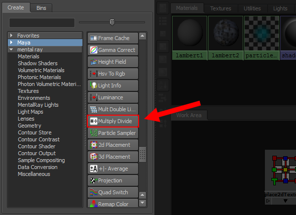
To illustrate the different color channels, we're going to experiment with a Multiply Divide node. This utility node can be found in the list which resides on left of the Hypershade. If the node is not present, highlight "Maya" in the other list to show the default set of shaders and utility nodes. You can also start typing the node name into the search bar found above these lists for quicker results. Once it is found, add a new Multiply Divide node to the Work Area by Middle-clicking it and dragging it to where you want it.
Delete the connection between the File and the shader. Middle-click the right side of the File and release on the Multiply Divide node. Select input1 from the resulting menu. Similarly, Middle-click the right side of the Multiply Divide node and release on the shader, selecting color from the options. If you want to make an unusual connection between nodes, select Other... from the menu.
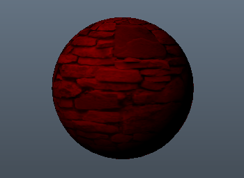
You now have a Multiply Divide node that receives a color from the File, manipulates it in some way, and then passes that color on to the shader. At the moment, you should notice no change in the shader besides the fact that your sphere got blurrier. This indicates that Default Quality Rendering is not up to the task. In the viewport, enable Renderer → High Quality Rendering or click  to get a better look at the shader.
In the Hypershade, double-click the Multiply Divide node. This should bring up the Attribute Editor. The value fields of Input 1 should be darkened, indicating a value is connected to them, and they should be mapped to the shader, as indicated by the arrow to the right of the values. The Input 2 values should be (1, 1, 1) by default. Try changing Input 2 to (1, 0, 0). This should turn your shader red. This is because the Multiply Divide node takes in every RGB color that the File gives it and then multiplies it by (1, 0, 0), which effectively drops the green and blue components of the color. Try various values for Input 2 and see how the shader is affected.
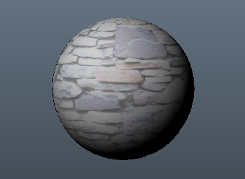
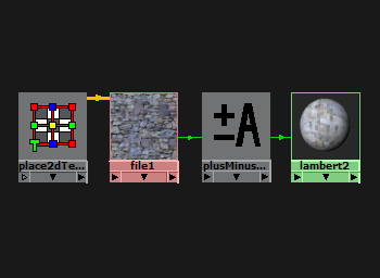
Most of the other shading nodes work in a similar manner. They take a number, manipulate it, and then pass it on. The Plus Minus Average node (labeled in Maya as +|- Average) provides a lot of functionality in one node. Map the color from the File into input3D[0] and map its output into the shader's color. In the Attribute Editor of the Plus Minus Average node, click Add New Item for Input 3D. Set the values for Input 3D[1] to (0.5, 0.5, 0.5). Notice that the shader becomes brighter.
This node now transforms (R, G, B) colors into (R + 0.5, G + 0.5, B + 0.5) colors. This means you can create RGB colors that lie outside the range of 0 to 1. However, this typically won't do you any good since the colors are eventually clamped back into the 0 to 1 range. Any color greater than (1, 1, 1) will go to white and any color less than (0, 0, 0) will go to black.
There are many, many other types of render nodes. We will briefly describe some of them here, but you will probably want to experiment with them on your own.
- The Reverse Node takes (R, G, B) colors and converts them to (1 - R, 1 - G, 1 - B) colors, which should be functionally equivalent to doing Invert in Photoshop.
- The Blend Colors node averages two colors based on a Blender value. If Blender is 0 then the color comes from Color 2, if Blender is 1 then the color comes from Color 2, and if Blender is some value in between then a weighted average is outputted.
- The Layered Texture node can created layers in a manner similar to Photoshop. The layers can then be blended according to different modes such as Over, In, Out, Add, Subtract, Multiply, Lighten, Darken, Saturate, etc. This node is fairly slow, so when possible do your layering in Photoshop and save it as a single texture.
- The Condition node picks between two colors based on a condition. The condition is evaluated by comparing two numbers.
- The Set Range node redistributes the range of a set of colors. For example, if the old range was 0 to 1 and the new range is 0.2 to 0.7, then a value of 0.5 would map to 0.45.