CSE 466 Lab 7: The AirStick
Introduction
In this lab, you will develop software for the AirStick, which is the air joystick you will use to control your player in the final soccer match. You will be given a working implementation which uses time-division multiplexing. Your objective for this lab is to develop an implementation that uses code-division multiplexing, evaluate its performance, and determine which implementation you are going to use for your player controller in the soccer match.
WARNING:
NEVER
attach or detach the iMote2 from the debug board, sensor board, SuperBird, or AirStick
when power is attached. ALWAYS
make sure you've unplugged ALL of the USB cables when connecting or disconnecting boards. (The one exception is the antenna board for the AirStick, which may be safely connected and disconnected while the system is operating.)
Objectives
In this lab, you will learn:
- how to extend the electric field sensor you built in Lab 3 to four channels
- how to implement code division multiple access (CDMA)
- how to translate the readings from the sensor to X, Y and Z coordinates
Hints
- Practice
incremental design. Take this lab step by step and test
along the way to make sure you understand your code and verify that it
is working as you expected. Coding the entire project then trying to
debug a problem can be challenging. Make sure to test pieces
of the assignment one at a time and convince yourself that they are
working before moving on to another piece.
- Utilize the JTAG debugger as you are developing your code for the ATmega16. However, be careful not to stop the execution of the AirStick firmware while the iMote2 is trying to do i2c communication, or the system could hang.
Suggested Reading and Resources
Part 1: Intro to the AirStick and Testing
- Obtain an AirStick and antenna board from a TA, and take a few moments to look over the AirStick board and schematic. The circuit should look very similar, but not identical, to the one you made in Lab 3:
- It uses an ATmega16 to perform measurements. You will program the ATmega16 to generate the signals for the transmit antennas, and use its ADC to make readings. These readings will be accumulated in the ATmega16 and then communicated to the iMote2 over I2C.
- The same op-amp circuit you used in Lab 3 is on the board. Notice that there are two independent receive channels, one for each antenna connector on the board. We're using a different op-amp that works at the lower supply voltage that the iMote2 provides, but the circuit is otherwise identical.
- A single LED (L1) is provided to aid debugging and provide status information to the user, next to the reset button (SW1) near the edge of the board.
- Two large connectors (J1 and J2) allow the antenna board to be plugged into either the left or right side of the board.
- The white connector on the edge of the board (P1) allows you to program the ATmega16 over the JTAG interface.
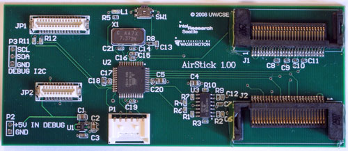 |
| Figure 1. The AirStick Board |
- Since the AirStick boards have not been extensively tested since we received them, you should make sure that your AirStick board is fully functional before proceeding to Part 2. In the remainder of Part 1, you will verify the functionality of your AirStick board. If you cannot complete any of the steps or the results are not as expected, exchange your AirStick for another.
- Connect the AirStick board to one of your iMote2s. Don't connect the SuperBird, basic sensor board, or debug board yet.
- Connect the iMote2 to a computer and push the power button. The green LED on the AirStick should turn on as soon as you connect the USB cable.
- Download the Linux driver code and airstick_dump application code contained in airstick.tar.bz2 to your attu account. Extract the archive (tar xjvf airstick.tar.bz2) and run make modules to compile the airstick.ko kernel module. Then, run make apps to compile the airstick_dump application. Copy both to your iMote2.
- insmod airstick.ko on the iMote2. dmesg should print a line indicating that it found an AirStick, and a device called airstick should be added to /proc/devices.
- Use mknod to create /dev/airstick corresponding to the major number for the AirStick and minor number 0.
- Now, run airstick_dump. The light on the AirStick should begin to blink at a rate of a few Hz. This indicates that it is actively making readings. (If it blinks, but at a slower rate, such as one blink per second, your AirStick has been misconfigured. Consult a TA.)
- If you connect the antenna board to the AirStick, you should see four measurements printed on each line, at a rate of several per second. These numbers are the values of the accumulators for the four channels on the AirStick. It should also print which side the antenna board is connected to. Verify that the numbers are in the range of 5000 to 20000. If you see different numbers, particularly zeros, something is wrong.
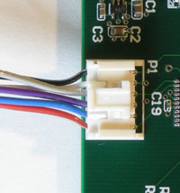
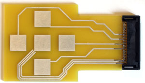 |
| Figure 2. The AirStick Antenna Board |
- Move your finger above the board and make sure that the numbers change accordingly. The columns printed correspond to the north, south, west, and east pads, respectively.
- Test with the antenna board connected to both sides of the AirStick.
- If all of the above steps were successful, you have a working AirStick and are ready to proceed.
Question 1. Notice that one of the channels has a consistently higher reading than the others. Why might this be? Note that the channel that exhibits this behavior changes depending on which side of the AirStick the antenna board is plugged into.
Question 2. Why is it advantageous to use an ATmega16 on the AirStick, rather than using the iMote2's GPIO pins to directly transmit and receive signals?
Part 2: Setting up the AVR development environment
- Download the AVR Studio project for the AirStick. This is the source code for the firmware that was pre-loaded onto your AirStick.
- Connect an AVR JTAGICEmkII interface to your AirStick board. The cable that you previously used to connect to your breadboard has been with replaced with a connector that fits the connector on the side of the AirStick board.
 WARNING: Be careful connecting and disconnecting the JTAG connector from the side of the AirStick board. Make sure you disengage the clip on the connector before attempting to remove it, and always pull on the plastic connector only, not the wires.
Also, note that the short adapter cables should stay attached to the JTAG units and be put away in the 466 storage cabinet, and NOT remain attached to your AirStick board when you put it away!
- Load the project in AVR Studio and take a moment to familiarize yourself with the code. The ADC_vect ISR should look familiar from Lab 3. Note how the I2C works; it is set up so that the iMote2 can read and write from "registers" on the AirStick. (These registers and their addresses are described in the readme.txt file.) The TWI_vect ISR handles the state machine for the I2C and calls the twi_set_reg and twi_read_reg functions when the I2C master requests writing and reading, respectively.
- Take some time to review the readme.txt file included in the AVR Studio project and make sure you understand the interface between the iMote2 and the AirStick.
- Change the last 4 bytes of the fw_id variable to a 4-character string of your choosing that identifies your group. Compile and run the firmware on the AirStick. When you insmod airstick.ko on the iMote2, you should see this string printed in dmesg. Verify that airstick_dump still works.
UPDATE: The readme.txt file seems to be missing from the airstick-avr zip file, so here it is separately.
Part 3: Implementing CDMA
Now you will modify the firmware on the AirStick so that it uses code-division multiplexing rather than time-division.
- First, implement the four linear feedback shift registers (LFSRs) that you will need to generate the pseudo-random sequences for the four transmit channels. You may decide how you want to implement the LFSRs. One way to do this is to implement the pseudocode in the lecture notes. Another possibility is to precompute the LFSRs, and store the sequence in a lookup table. (Remember to store this table in program memory and use the LPM macro to read from it.) You should choose different starting states for each of the LFSRs so that each channel will be transmitting a different pseudo-random sequence (or more accurately, a different position in the same pseudo-random sequence.)
- Modify the program so that instead of transmitting a square wave on one channel at a time, different pseudo-random sequences are transmitted on each channel simultaneously.
- Now, modify the program so that the received signal is demodulated by each of the four pseudo-random carriers. You should demodulate the received signal into four accumulators, for 255 samples, and then make the final values of the accumulators available to the iMote2. Then, you should clear the accumulators and begin sampling again.
- Try not to change the existing I2C protocol or register locations, so that your implementation of the firmware remains compatible with the Linux driver. You can, however, add new functionality as you feel it is appropriate.
Question 3. Compute the vector of all possible states of the 8-bit LFSR you implemented above. Now, compute the inner product of the LFSR with itself, and then the inner product of the LFSR with itself with a few different offsets (e.g. for(i=0; i<255; i++) acc += lfsr[i] * lfsr[(i+offset) % 255]; ). Explain, based on your findings, why CDMA using an LFSR to generate pseudo-random sequences works.
Question 4. Try computing of the inner product of only part of the LFSR with itself, both with an offset of 0 and with some other offset. What happens to the property you discovered above? Why is it important that nsamps be 255 with this particular LFSR?
Part 4: Computing X, Y and Z coordinates
In this part, you will transform the raw readings from the four channels of the AirStick into X, Y, and Z coordinates that you will use to move a square on the LCD screen, and later, your player in the soccer match.
To begin, you should write a user application on the iMote2 that reads the raw values of the accumulators and does the computation in software. As you refine your algorithm, you may wish to move this calculation into the ATmega16 on the AirStick to reduce the load on the iMote2. This is optional.
- You may use either the provided TDMA firmware or your CDMA firmware for this part. You should make a preliminary evaluation of the performance of the two implementations and decide which will yield better results.
- Implement a calibration routine similar to the one you may have used in Lab 4. During the calibration period, you should record the minimum and maximum values for each of the four channels as you move a finger over the board (but be careful not to touch it!) You can then use the minimum value and the difference between the minimum and maximum values to scale the raw readings to a range of your choosing. Choose this range to fairly closely match the difference between the minimum and maximum values you see. If you make the range smaller, you will lose precision for the next calculation. Making it bigger is unnecessary.
- At this point, you should have written a new version of airstick_dump that performs your calibration routine and then prints out your scaled values. Each channel should have the same range of values, and there should be no offsets in the scaled values between the channels. Also, you should handle the edge cases gracefully; if a value exceeds your range, you should constrain them rather than exceeding the range or overflowing.
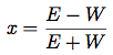
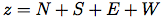
- You can do a basic conversion to X, Y, and to some extent Z coordinates with the following equations, where N, S, E, and W refer to the north, south, east, and west sensor pads:
- Use your scaled values from the step 3 to compute the above functions. You'll likely find that these equations work well for a certain range, but outside that range, they behave poorly. You should therefore limit the range of the values. You will also likely find it beneficial to do a second calibration for your X-Y values.
- Note that the above functions will produce fractional values, which you will want to scale to the range of X and Y values you want. Remember to multiply by this scale factor before you divide, or the result will always be zero.
- Write a new version of airstick_dump that prints out X and Y coordinates.
- The Z-axis is a bit noisier than the X and Y axes, but you should be able to use it to detect the difference between a finger nearby the board and no finger. Make your airstick_dump application so that it only prints values when a finger is nearby.
- Once you have X and Y coordinates working reasonably well, re-use your code from Lab 6 to produce a square on the LCD that roughly corresponds to the position of your finger over the sensor.
Part 5: Making it better; Evaluation
Now, try to make your AirStick work as well as you can for generating X, Y, and Z coordinates. Remember that this is how you will control your player in the soccer match, so it is to your advantage to make it work as well as possible.
One area you might want to investigate is doing some averaging (using the method for computing running averages you learned in earlier labs) of either the X, Y, and Z axes, or of the raw readings from the AirStick. Try to keep a balance between reducing noise and keeping the sensor responsive.
Feel free to make changes to the firmware, kernel module, and your user application. If you are not confident in your CDMA firmware, try to improve the provided TDMA firmware.
When you are finished, evaluate the performance of your CDMA implementation against the TDMA implementation. It would be excellent if you could make some quantitative measurements, such as the signal/noise ratio. This is a measure of how much the sensor value changes based on the presence/absence of a finger, divided by the amount of random variations in the readings when a finger is not present or is held at a constant distance from the sensor. Decide, based on your findings, which implementation you are going to use in the final lab. Summarize your findings and your reasons for your decision in your lab write-up.
When comparing the CDMA and TDMA implementations, make sure to make a fair comparison. It makes sense to compare the performance when both systems are providing approximately the same number of 4 channel updates per second. So, assuming that the ADC time dominates everything else, you should compare 255 ADC samples (demoded 4 times by CDMA) to 64 ADC samples per channel demoded by TDMA.
Both partners should prepared to discuss their evaluation with the TAs during check-off.
Deliverables
- The following files should be turned in:
- A zip file or tarball containing the code for your kernel module
- A zip file or tarball containing the code for any user applications you've written
- A zip file containing the AVR studio project for your CDMA implementation, including your modified readme.txt file if you made any changes
- Your answers to the questions (.txt, .rtf, .pdf, or .doc;
NO .docx)
- Submit files to the Catalyst drop box for your section:
- Demonstrate
your completed lab to a TA during the first half-hour of
next week's lab period.