Project 1:
Feature Detection and Matching
Renshu Gu
Student# 1222208
1. Harris Corner Detection
Harris corner detection can be implemented
in the following 4 steps:
//--------------------------------------------------------------------------
//
STEP 1:compute image Ix2,Iy2 and Ixy
//--------------------------------------------------------------------------
//--------------------------------------------------------------------------
//
STEP 2: Gaussian smooth to denoise
//--------------------------------------------------------------------------
//5*5
gaussian template
//normalization:
can be omitted
//Gaussian
smooth
//--------------------------------------------------------------------------
//
STEP 3: compute corners of image
//--------------------------------------------------------------------------
//cim: corners of image
for(i = 0; i < h; i++)
{
for(j = 0; j < w; j++)
{
//add a small number to denominator
cim(i,j) = (Ix2(i,j)*Iy2(i,j) - Ixy(i,j)*Ixy(i,j))/(Ix2(i,j) + Iy2(i,j) + 0.000001);
}
}
//--------------------------------------------------------------------------
//
STEP 4: compute local maximum to find cornors
//--------------------------------------------------------------------------
//local
maximum
const double size=3;
double max;
//find
the max value in neighborhood
for(i = 0; i < h; i++)
{
for(j = 0; j < w; j++)
{
max=-1000000;
if(i>int(size/2) && i<h-int(size/2) &&
j>int(size/2)
&& j<w-int(size/2))
for(int m=0;m<size;m++)
{
for(int n=0;n<size;n++)
{
if(cim(i+m-int(size/2),j+n-int(size/2))>max)
max=cim(i+m-int(size/2),j+n-int(size/2));
}
}
if(max>0)
mx(i,j)=max;
else
mx(i,j)=0;
}
}
//decide
harris corner
//const double thresh=4500;
for(i = 0; i < h; i++)
{
for(j = 0; j < w; j++)
{
if(cim(i,j)==mx(i,j)) //get local
max value
//store results to harrisImage, grayscale turn into 0-1
harrisImage.Pixel(j,i,0)=mx(i,j)/255.0f;
}
}
2. Feature description
I added 2 files in the sln,
MySift.cpp and MySift.h. I use mySIFT
to be the descriptor. mySIFT
basically applies SIFT descriptor. Since Harris is mono scale, it cannot be
applied to my SIFT without “multi-scale processing”. I planned to multi-scale
Harris corners to SIFT, but I haven’t been able to implement this plan. Below
are the key stages of descriptors
Key stages
Here are the key parts in SIFT that are implemented
in the turned-in codes
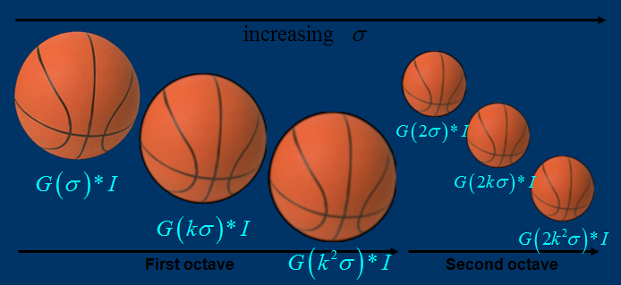
Scale-invariant feature detection
Lowe's method for image feature generation
transforms an image into a large collection of feature vectors, each of which
is invariant to image translation, scaling, and rotation, partially invariant
to illumination changes and robust to local geometric distortion. These
features share similar properties with neurons in inferior temporal cortex that are
used for object recognition in primate vision.[4] Key
locations are defined as maxima and minima of the result of difference of Gaussians function
applied in scale space to a series of smoothed and resampled images.
Low contrast candidate points and edge response points along an edge are
discarded. Dominant orientations are assigned to localized keypoints.
These steps ensure that the keypoints are more stable
for matching and recognition. SIFT descriptors robust to local affine
distortion are then obtained by considering pixels around a radius of the key
location, blurring and resampling of local image orientation planes.
Each of the SIFT keypoints
specifies 2D location, scale, and orientation, and each matched keypoint in the database has a record of its parameters
relative to the training image in which it was found. The similarity transform
implied by these 4 parameters is only an approximation to the full 6
degree-of-freedom pose space for a 3D object and also does not account for any
non-rigid deformations. Therefore, Lowe[3] used
broad bin sizes of 30 degrees for orientation, a factor of 2 for scale, and
0.25 times the maximum projected training image dimension (using the predicted
scale) for location. The SIFT key samples generated at the larger scale are
given twice the weight of those at the smaller scale. This means that the
larger scale is in effect able to filter the most likely neighbours
for checking at the smaller scale. This also improves recognition performance
by giving more weight to the least-noisy scale. To avoid the problem of
boundary effects in bin assignment, each keypoint
match votes for the 2 closest bins in each dimension, giving a total of 16
entries for each hypothesis and further broadening the pose range.
Feature descriptor: orientation and
magnitude in neighborhood
The descriptor is designed such that it
gives orientation and magnitude information of each key point.

Where m(x,y) is magnitude and ![]() (x,y)is the orientation. L is the scale
the point is at.
(x,y)is the orientation. L is the scale
the point is at.
When implementing, we need to compute the orientation
and magnitude of points in a neighborhood, and sum into a histogram with 36
bins (every bin stores orientation within 10 degrees).

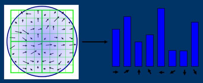
Identify peak and assign orientation and
sum of magnitude to key point.
For more details about SIFT, please visit:
http://en.wikipedia.org/wiki/Scale-invariant_feature_transform#Scale-invariant_feature_detection
outline of the MySift codes:
//key
parts in mySIFT
//mySIFT STEP 1: preprocessing the image
CvMat *ScaleInitImage(CvMat * im)
;
//initialize
//mySIFT STEP 2: build Gaussian pyramid function
ImageOctaves* BuildGaussianOctaves(CvMat * image,ImageOctaves*
DOGoctaves) ;
//build Gaussian
//mySIFT STEP 3: Detect Keypoint
Keypoint DetectKeypoint(int
numoctaves, ImageOctaves *GaussianPyr,ImageOctaves* DOGoctaves,IplImage*
haarmask);
void DisplayKeypointLocation(IplImage* image, ImageOctaves *GaussianPyr,Keypoint keypoints);
void
DisplayKeypointLocation1(IplImage* image, ImageOctaves *GaussianPyr,Keypoint
keypoints);
//mySIFT STEP 4: Compute gradient and magnitude,
decide the major orientation of each key point
void ComputeGrad_DirecandMag(int numoctaves,
ImageOctaves *GaussianPyr,ImageOctaves
*mag_pyr,ImageOctaves *grad_pyr);
int FindClosestRotationBin
(int binCount, float
angle); //HOG
void AverageWeakBins
(double* bins, int binCount); //filter HOG
//
bool InterpolateOrientation
(double left, double
middle,double right, double *degreeCorrection, double *peakValue);
//decide
major orientation
Keypoint AssignTheMainOrientation(int
numoctaves, ImageOctaves *GaussianPyr,ImageOctaves *mag_pyr,ImageOctaves
*grad_pyr,Keypoint keypoints);
//DisplayOrientation
void DisplayOrientation
(IplImage* image, ImageOctaves
*GaussianPyr,Keypoint keypoints);
//mySIFT STEP 5:Extract Feature
Descriptors of key points
void ExtractFeatureDescriptors(int numoctaves,
ImageOctaves *GaussianPyr,Keypoint
pts);
3. Feature matching and indexing
Instead of Lowe’s matching algorithms
for sift, this project simply uses ssd
and ratio test methods to find matches.
4. experiments and results
Features roc featurefile1 featurefile2 homographyfile [matchtype] rocfile aucfile
ROC results of mySIFT

ROC for yosemite

Threshold
selection for yosemite

ROC for graf

Threshold selection for graf
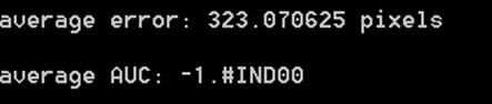
Obviously there’s problem with graf, which I haven’t figured out. But I do know that the performance of matching is not so good with graf images as I plotted the matched point pairs.
Features
benchmark imagedir [featuretype
matchtype]
Note that in command “Features benchmark…”, ratio test method has no threshold.
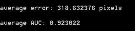
The AUC results for other image sets are:
Bike
Matchtype: ssd

Matchtype: ratio
Graf-AUC error!
Matchtype: ssd
Matchtype: ratio
Leuvue
Matchtype: ssd

Matchtype: ratio

Wall
(takes
a long time to compute)
Matchtype: ssd

Matchtype: ratio
