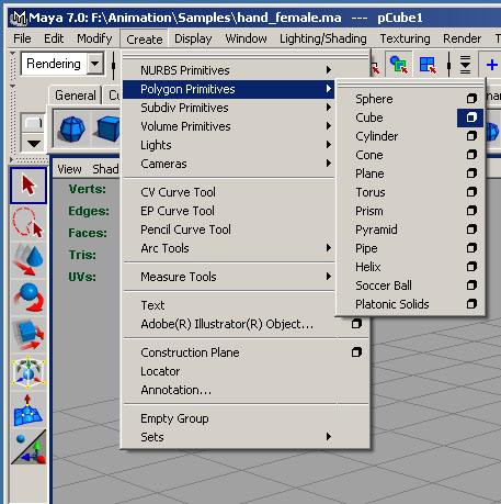
 Polygon Cube Options menu.
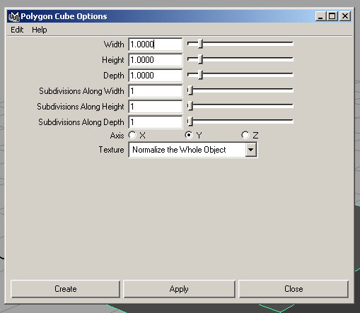 Default Options.
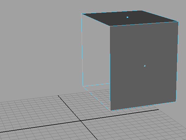 Since the wii controller is symmetrical, we can position the cube on one side of the X axis and delete the face that's aligned on that axis.
For a better view of how the final controller will look when you move the vertices around, switch back and forth between Subdivision (Modify > Convert > Polygons to Subdiv options) and polygon mode (Modify > Convert > Subdiv to Polygons options). This will allow you to work on a smoothed version of the finger without actually having to add a lot of polygons the way that the Smooth function does. (Note: An alternative to use Subdivisions is to use the Smooth Proxy function. Polygons > Smooth Proxy.) This will allow you to see what a smoothed version of your model will look like as you are working on the low poly version. It is entirely up to you how you want to approach it.
The reason we use SubDiv or Smooth Proxy is because if we had a fully smoothed hand, it would be extremely hard to work with due to the high volume of faces, edges and vertices. So, we start with a low poly model and slowly up the polygon count as we need more detail. A basic rule of modeling is only to use as many polys as needed for the object. Any extra faces/edges/vertices becomes unwanted overhead during the rigging and rendering stages.
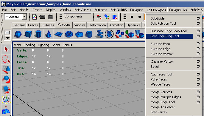 The Split Edge Ring tool is a very useful tool in the modeling process. You'll be using this very often.
 Starting dividing up the cube with edges.
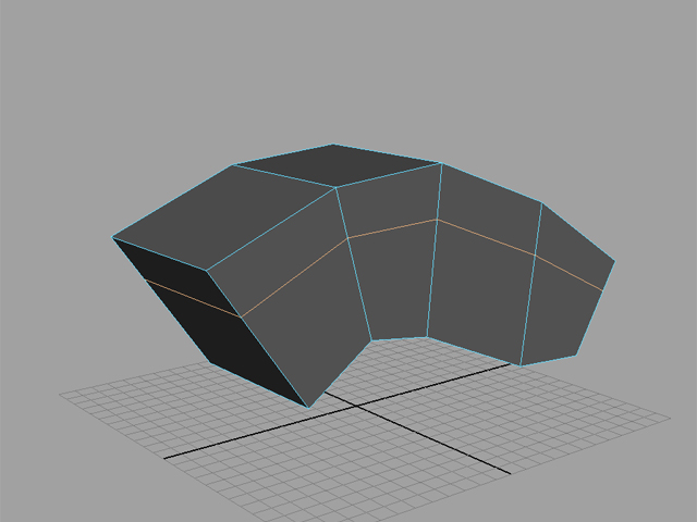
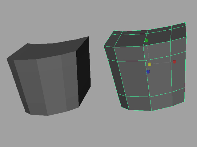
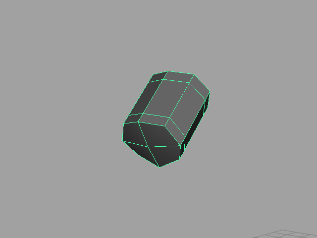
 Move Vertices around until the cube starts taking the form of the controller..
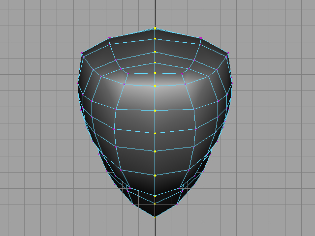
 Top and Front View.
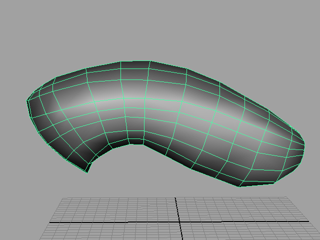
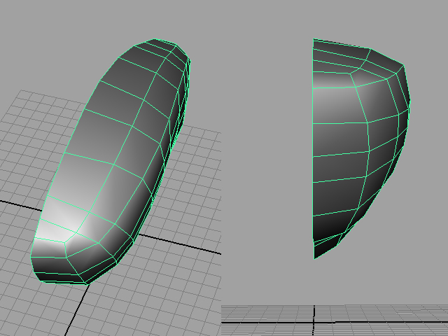
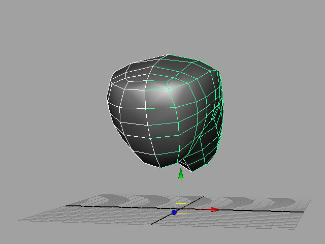
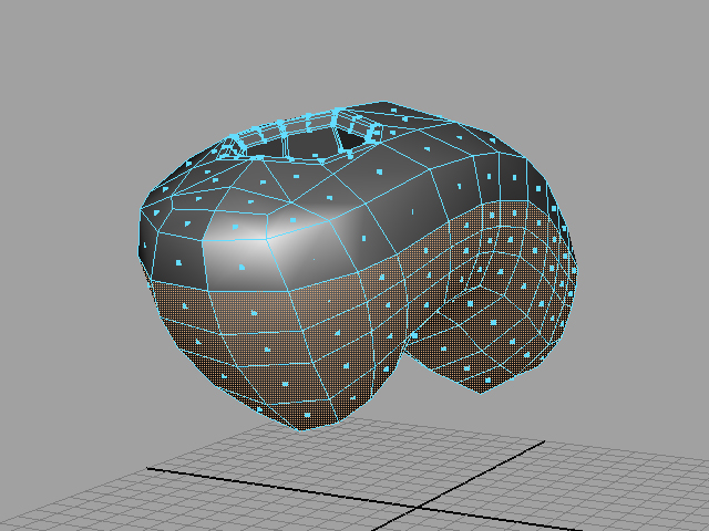
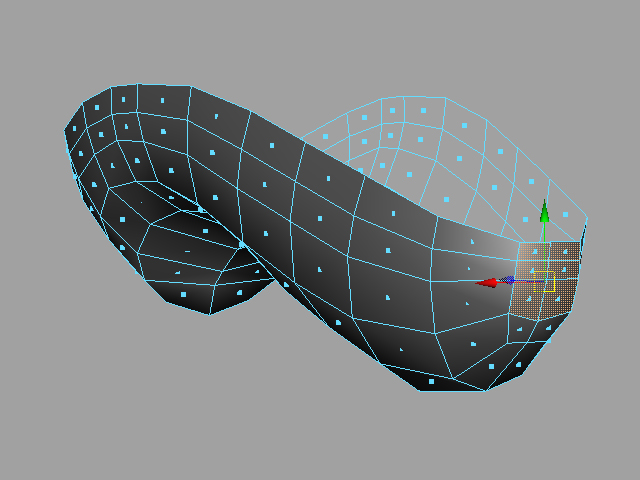
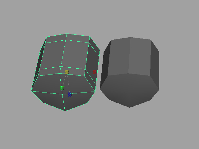
 Switch to SubD mode in order to see how a smoothed version of the wii controller will look.
 Duplicate the current model over the X axis. Make sure that X scale is set to -1 and that your pivot is along the origin.
 Combine by doing the Polygon > Combine operation and then merging all the connection vertices together with the Edit Polygons > Merge Vertices.
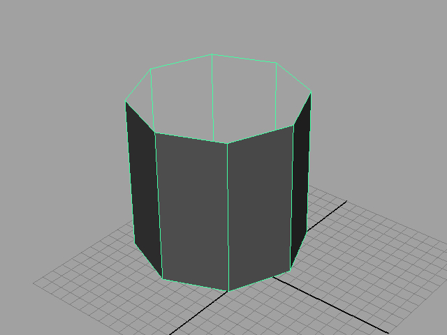
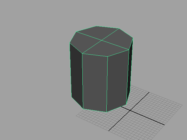
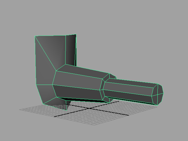
Create a cylinder with 8 sides and delete the top and bottom faces.
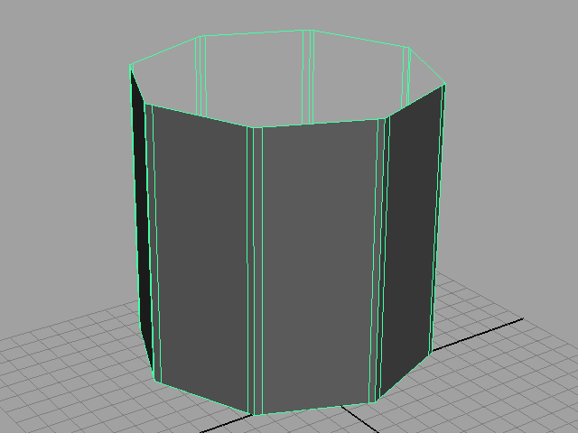
Add supporting edges to each edge in order to harden the sides of the cylinder.
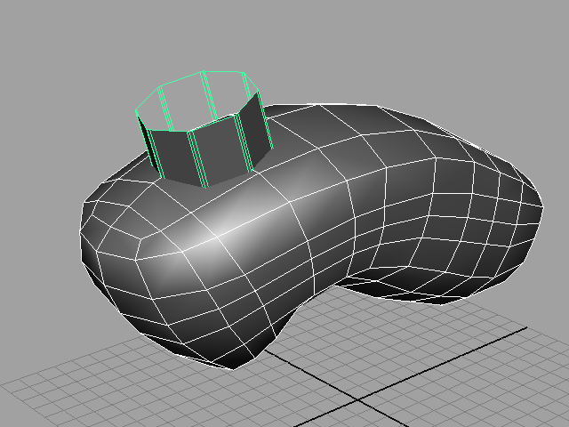
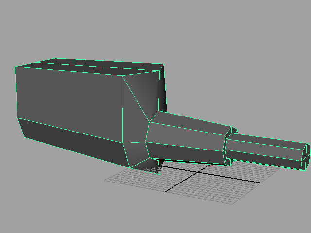
Position the cylinder and use the boolean tool to add the cylinder shape onto the main wii controller mesh.
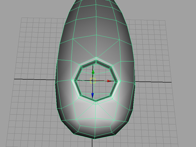
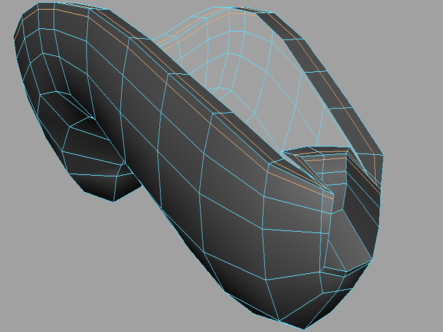
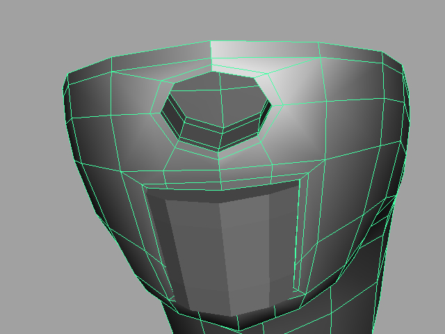
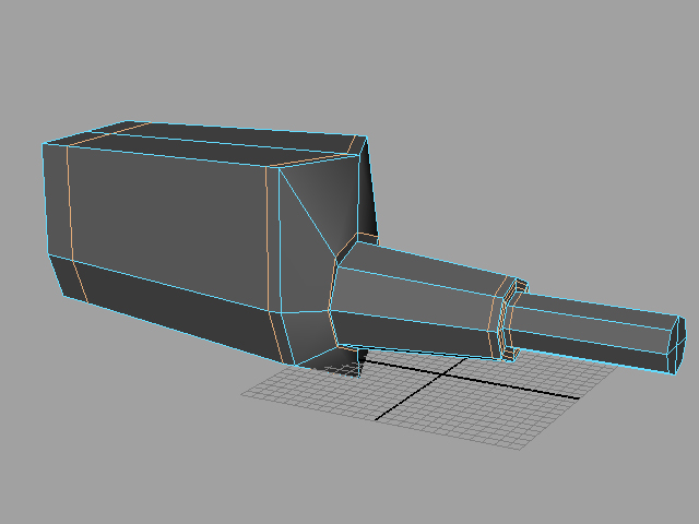
We will need to connect and delete edges in order to clean up the boolean operation. Vertices will need to be moved in order to make the surface smooth again after the boolean operation.
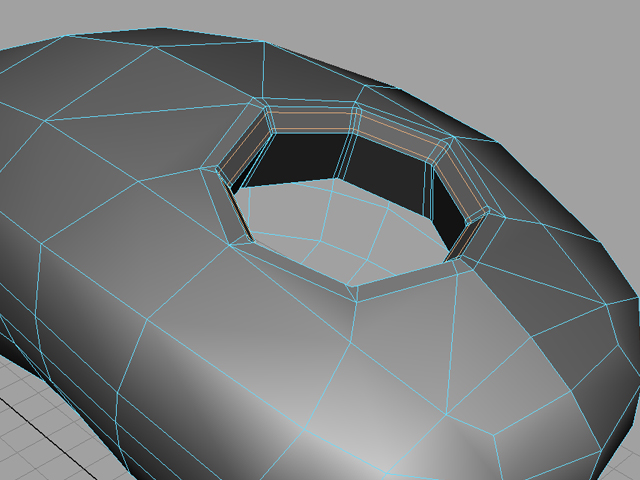
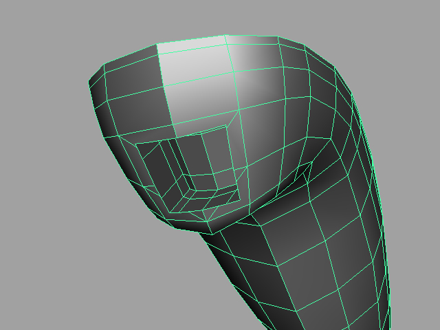
Add supporting edges to make the hole shape more ridged.
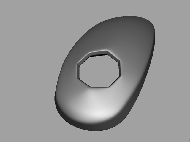
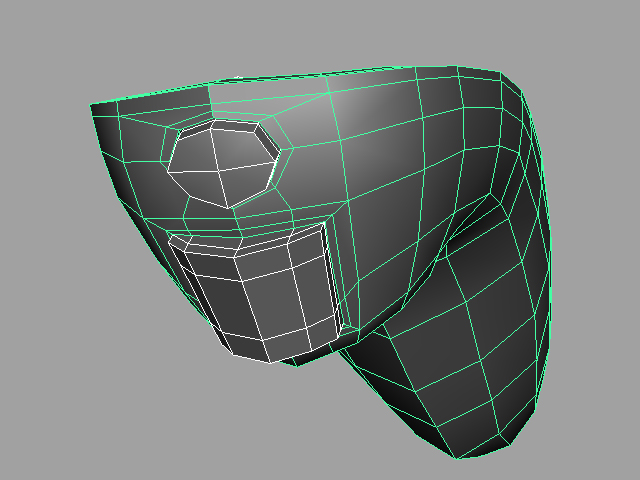
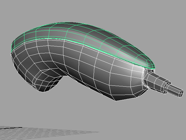
What the mesh looks like afterwards when in SubD mode or smoothed.
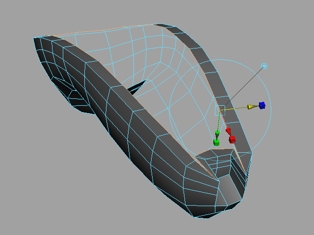
Select the faces for the bottom (or top) half of the controller.
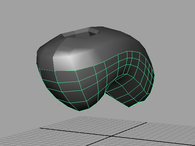
Use the extract tool to seperate the two halves from each other.
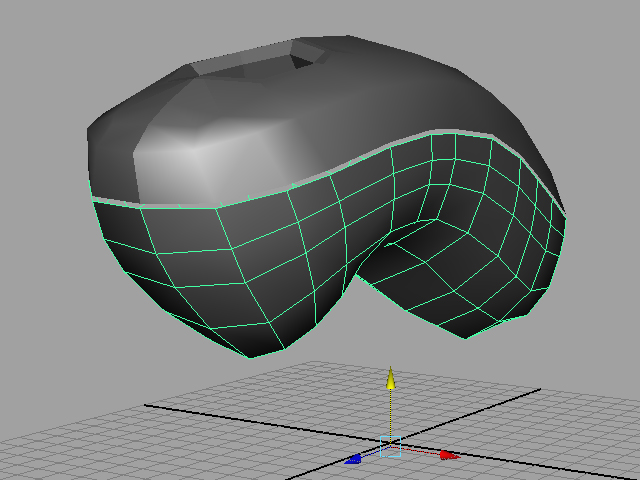
Move the bottom half a little bit lower to give some space for the indent.
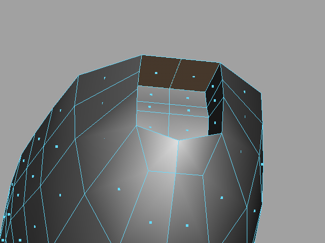
Extrude the edges inwards.
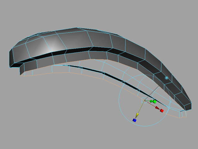
Extrude the new edge downwards
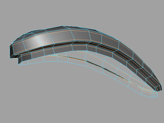
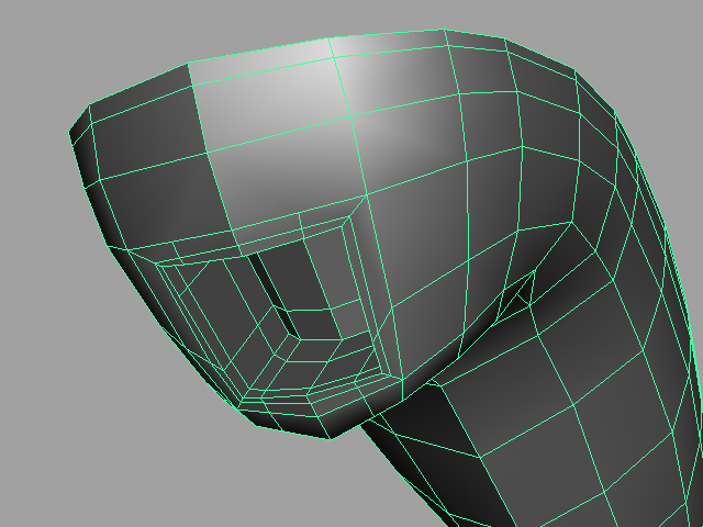
Add edge loops to make the borders more ridged.
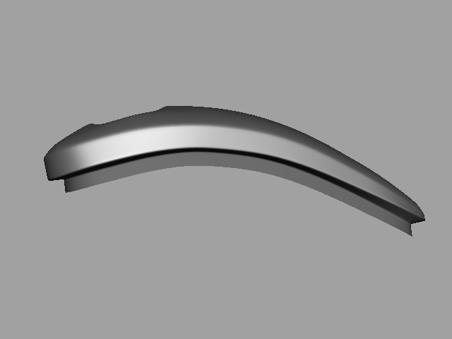
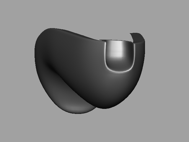
Check to see how the controller looks in SubD/Smooth mode.
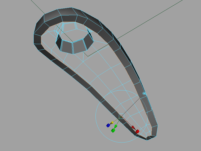
Select the faces where the hole will be created.
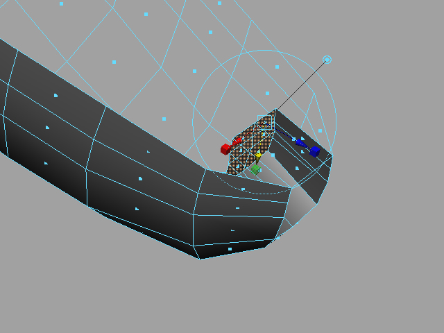
Extrude inwards towards the middle of the controller
Delete unnecessary faces.
Extrude inwards with the border edge.
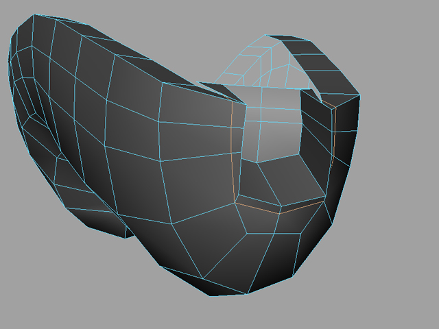
Use the split polygon tool to add edges next to the cable area of the controller.
Add support edges with the Edge Ring tool.
Add some edges to the front in order to make that area sharper.
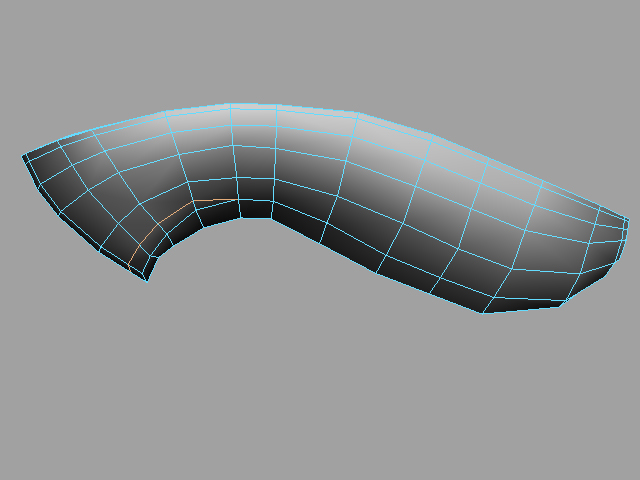
What it looks like in SubD mode.
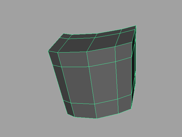
Creat a cube and add edges, move vertices and shape it into the button.
Duplicate the button and enlarge it a bit. This will be used to create the hole on the controller.
Select the Controller first, then the duplicate button, and use Polygons > Boolean > Difference
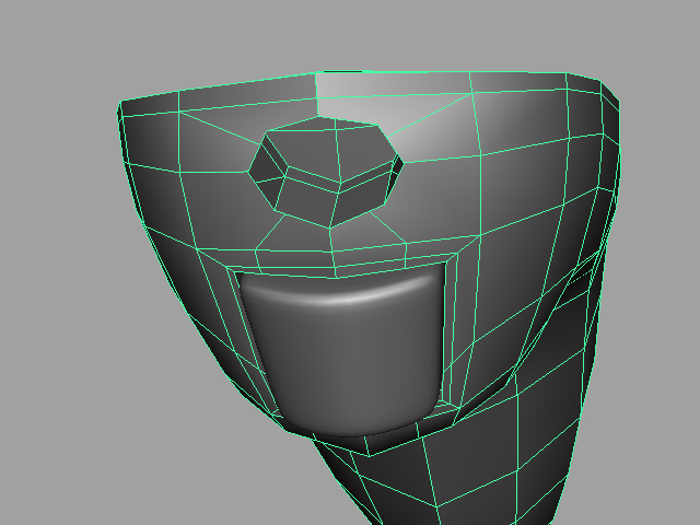
Clean up the boolean operation by connecting orphaned edges, deleting unneeded edges, and adding edges to help with smoothing it out. You'll have to tweak the vertices to get it to look smooth again.
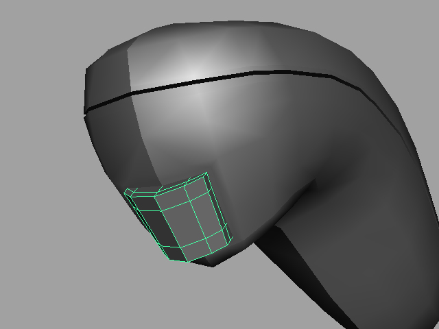
Position the button into the controller.
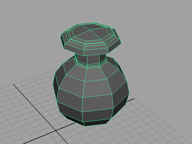
Create 8 sided cylinder.
Reshape until it looks like the reference button.
Duplicate the button and enlarge it a bit. This will be used to create the hole on the controller.
Select the Controller first, then the duplicate button, and use Polygons > Boolean > Difference
Clean up the boolean operation by connecting orphaned edges, deleting unneeded edges, and adding edges to help with smoothing it out. You'll have to tweak the vertices to get it to look smooth again.
Position the button into the controller.
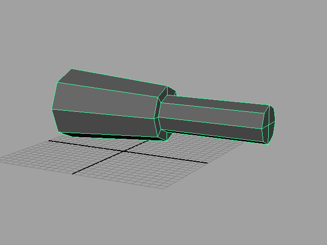
Extrude faces from the cylinder. Shape and resize areas as needed.
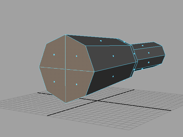
Delete the faces on the front of the cord.
Extrude the edges outwards.
Extrude the edges again to give the connecting part shape.
Add support edges (Edge Ring Tool/Split Polygon Tool) to harden the surfaces.
Relocate and reposition the cord into the controller. Move vertices around as need to make it fit better.
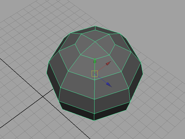
Create 8x8 sphere.
Extrude the top of the sphere to get the stick part out.
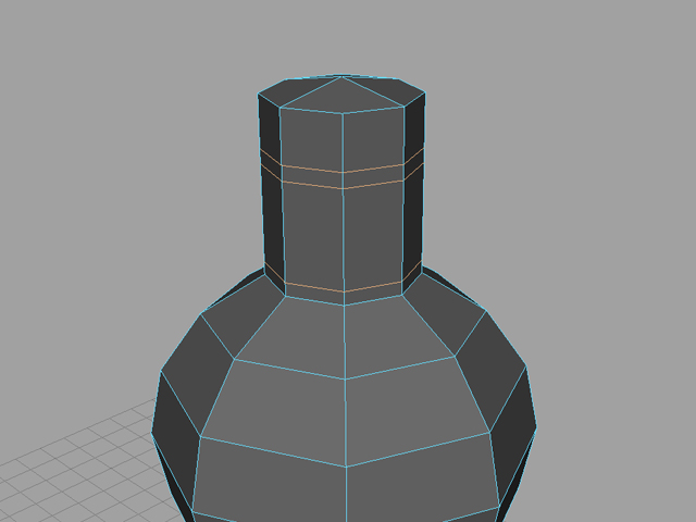
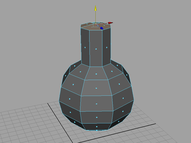
Add edge loops.
Move vertices around as needed to get our shape.
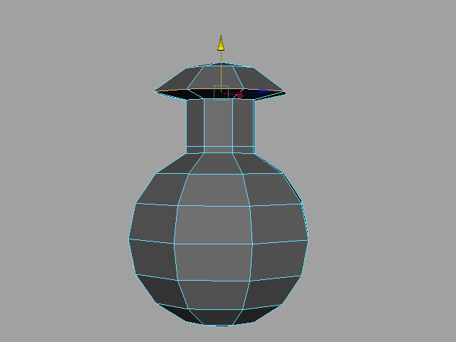
Keep adding edge loops and moving edges/vertices around until it looks like the reference.

Top view.
Bottom view.
Side view.
Front view.
Subdivision mode.
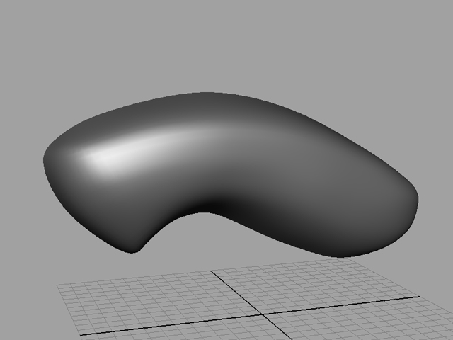
Smooth mode.